MANUAL | QUICK START GUIDE
CORSAIR RS II ARGB Series
PWM FANS
In this Guide
CONTENTS
120mm Single Fan
- One (1) RS II ARGB Fan
- Four (4) Mounting Screws
- One (1) ARGB Extension Cable
- One (1) PWM Extension Cable
140mm Single Fan
- One (1) RS II ARGB Fan
- Four (4) Mounting Screws
- One (1) ARGB Extension Cable
- One (1) PWM Extension Cable
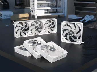
360mm Triple Fans
- One (1) RS II ARGB Unified Frame Fans
- Four (4) Mounting Screws
| a. Female ARGB Connector | c. Female PWM Connector |
| b. Male ARGB Connector | d. Male PWM Connector |
FAN INSTALLATION
BEFORE YOU START
IMPORTANT: Turn the computer off prior to the installation of the RS II ARGB fans.
IMPORTANT: Before connecting multiple fans to a single PWM header, check your motherboard manual for its maximum current limit. Ensure the total current requirement of your fans does not exceed this limit. Please refer to the "POWER RATING" section at the bottom of this Quick Start Guide.
1. INSTALL THE RS II ARGB FAN(S) INSIDE THE CASE
- Mount the RS II ARGB fans in your case with the supplied (B) mounting screws.
2. CREATE A FAN GROUP - SINGLE FANS
- Daisy-chain each fan’s PWM connector from one fan to the next until the chain is complete.
- The final PWM connector will be used later to connect the fan group to your motherboard.
* Skip this step if you plan to use the RS II ARGB fan individually.
3. CREATE AN ARGB GROUP - SINGLE FANS
- Daisy-chain each fan’s ARGB connector from one fan to the next until the chain is complete.
- The final ARGB connector will be used later to connect the fan group to your motherboard.
* Skip this step if you plan to use the RS II ARGB fan individually.
4. CREATE A FAN GROUP - 360 UNIFIED FRAME FANS
- Each 360 Unified Frame Fan includes a 600mm PWM cable and a 50mm PWM daisy-chain cable.
- Daisy-chain each fan group by connecting the 50mm PWM cable to the RS360 II ARGB Unified Frame Fans to the PWM connector on the next RS II ARGB fan.
- The remaining 600mm PWM cable will be used later to connect the fan group to your motherboard.
* Skip this step if you plan to use the RS II ARGB fan individually.
5. CREATE AN ARGB GROUP - 360 UNIFIED FRAME FANS
- Each 360 Unified Frame Fan includes a 600mm ARGB cable and a 50mm ARGB daisy-chain cable.
- Daisy-chain each fan group by connecting the 50mm ARGB cable from the RS360 II ARGB Unified Frame fans to the ARGB connector on the next RS II ARGB fan.
- The remaining 600mm ARGB cable will be used later to connect the fan group to your motherboard.
* Skip this step if you plan to use the RS II ARGB fan individually.
6. CONNECT FAN(S) TO 4-PIN FAN HEADER
- Single Fans: Connect the PWM group to the PWM extension cable (D), then into an available 3-pin or 4-pin fan header on your motherboard or fan controller.
- A 4-pin header is necessary for PWM control. Ensure that the fan connector guides line up with the guide on the fan header.
- 360 Unified Frame Fans: Connect the 600mm PWM cable directly into an available 4-pin PWM header on your motherboard or fan controller
- A 4-pin header is necessary for PWM control. Ensure that the fan connector guides line up with the guide on the fan header.
7. CONNECT FAN TO A +5V ARGB HEADER
- 360 Unified Frame Fans: Connect the ARGB group to the ARGB extension cable (C), then into an available +5V ARGB header on your motherboard or fan controller.
- Ensure that the arrow indicator on the ARGB connector is aligned with the +5V pin on the +5V ARGB header.
- 360 Unified Frame Fans: Connect the ARGB group to the ARGB extension cable (C), then into an available +5V ARGB header on your motherboard or fan controller.
- Ensure that the arrow indicator on the ARGB connector is aligned with the +5V pin on the +5V ARGB header.
FAN SETUP
1. CONFIGURE FAN SPEED
Fan speeds are configured and managed by the devices to which the 4-pin cable is connected. In most situations this is typically the motherboard via a fan header, which would require entering BIOS to configure fan speeds. Please refer to your motherboard manual for additional details.
2. CONFIGURE FAN LIGHTING
Fan lighting is configured and managed by the device to which the +5V ARGB cable is connected. In most situations, this is typically the motherboard via a +5V ARGB header. Please refer to your motherboard manual for additional details.
Motherboard manufacturers typically offer software to control fan speeds and RGB lighting, so find out which software is offered for your motherboard to control the fans using that method.
FREQUENTLY ASKED QUESTIONS
Can I connect the 4-pin cable connector into a 3-pin fan header on the motherboard or fan controller?
Yes, you can, but keep in mind, installing a 4-pin connector on a 3-pin header will no longer benefit from PWM control.
In which direction does the air flow?
CORSAIR fans have little arrows on the side of the fan frame that indicate the direction the fan blades spin as well as the direction in which the air flows.
How many fans can I chain together?
Most motherboard fan headers can typically provide up to 1A, which would be about 3 fans.
POWER RATING
RS120 II ARGB Input Rating: 12V max 0.4A / typical 0.17A | 5V max 0.3A / typical 0.3A
RS140 II ARGB Input Rating: 12V max 0.45A / typical 0.18A | 5V max 0.3A / typical 0.3A
RS360 II ARGB Input Rating: 12V max 1.2A / typical 0.51A | 5V max 0.9A / typical 0.9A
WARRANTY

CORSAIR RS II ARGB Series fans have a 5-year warranty.
LEGAL
© 2026 CORSAIR MEMORY, Inc. All rights reserved. CORSAIR and the sails logo are registered trademarks of CORSAIR in the United States and/or other countries. All other trademarks are the property of their respective owners. Product may vary slightly from those pictured.
RELATED CONTENT