En bref
Si votre câble 12 V-2x6 devient trop chaud, généralement parce que le connecteur n'est pas correctement branché sur la carte graphique, ThermalProtect le détecte et ordonne à la carte graphique de réduire son intensité avant que l'appareil ne surchauffe. Pour ce faire, il utilise un petit interrupteur thermique intégré directement dans le peigne du câble, situé à 30 mm du connecteur de la carte graphique. Aucun logiciel n'est requis, aucune mise à jour du micrologiciel n'est nécessaire et aucune exigence particulière n'est imposée au bloc d'alimentation, si ce n'est la présence d'un port 12 V-2x6 standard.
Voilà en résumé. Si vous voulez comprendre pourquoi ce problème existe, comment la solution fonctionne réellement d'un point de vue physique et ce qui se passe étape par étape lorsqu'elle se déclenche, poursuivez votre lecture.
Comment nous en sommes arrivés là : le 12VHPWR et le problème des connecteurs qui brûlent
De nombreux câbles à un seul
Pendant des années, pour alimenter un GPU haut de gamme, il fallait brancher deux, voire trois câbles PCIe à 8 broches. D'un point de vue électrique, cela fonctionnait très bien : répartir la charge de courant sur plusieurs connecteurs évitait de surcharger une seule connexion. Mais d'un point de vue pratique, c'était un véritable casse-tête. Plus de câbles signifiait plus d'encombrement, une circulation d'air moins efficace et davantage d'éléments à acheminer et à gérer à l'intérieur du boîtier.
Le PCI-SIG, le groupe industriel chargé de définir les normes PCIe, a résolu ce problème avec le 12VHPWR : un connecteur haute densité capable de supporter jusqu’à 600 W via 12 broches d’alimentation. Un seul câble vers le GPU, c’est simple et efficace. Sur le papier, une amélioration évidente.
Le problème que personne n'avait vu venir
C'est alors que les signalements ont commencé à affluer. Un nombre restreint, mais difficile à ignorer, de connecteurs 12VHPWR prenaient feu : le plastique fondait, les broches étaient brûlées et, dans certains cas, les connecteurs d'alimentation du GPU étaient également endommagés.
Le problème provient d'une tolérance de conception du connecteur 12VHPWR d'origine, qui permet aux broches de détection d'entrer en contact avant que les broches d'alimentation ne soient complètement enfoncées, ce qui permet la mise sous tension du système même en cas d'insertion partielle. Cela signifie qu'un câble qui semble branché et détecté par le GPU comme tel peut tout de même présenter des broches d'alimentation qui ne sont qu'à moitié enfoncées dans leurs prises. Un contact partiel entraîne une résistance plus élevée au niveau de chaque broche. Une résistance plus élevée, compte tenu du courant que ces câbles transportent (nous parlons de 50 ampères à travers le connecteur à 600 W / 12 V), génère de la chaleur par simple effet Joule : P = I² × R. Il s'agit d'une faible augmentation de la résistance, mais le courant est au carré. La chaleur s'accumule rapidement, et ce, directement au niveau de la broche.
Le phénomène de Joule en termes simples
La résistance électrique transforme le courant en chaleur. Si la résistance double, la chaleur double. Si le courant double, la chaleur quadruple. À 50 A, même une faible augmentation de la résistance de contact, de l'ordre de quelques milliohms, génère suffisamment de chaleur pour endommager l'isolation.
12V-2x6 : la solution mécanique
Le PCI-SIG a révisé la norme et publié la version 12V-2x6. La géométrie du boîtier du connecteur est identique à celle du 12VHPWR. Même coque, même encombrement, compatibilité totale avec les versions antérieures. Ce qui a changé, c'est l'intérieur : les broches de détection ont été raccourcies par rapport aux broches d'alimentation.
Cette simple modification a comblé la faille liée à l'insertion partielle. Désormais, le connecteur doit être entièrement inséré, les broches d'alimentation étant bien en place, avant que les broches de détection n'entrent en contact. Si les broches de détection ne sont pas en contact, le GPU ne fonctionnera pas correctement. La conception mécanique garantit désormais ce qui aurait dû l'être dès le départ.
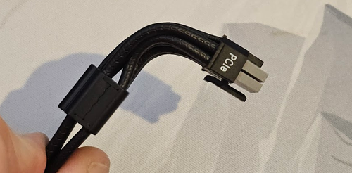
Le câble ThermalProtect de CORSAIR va encore plus loin grâce à ses embouts de connecteur gris à code couleur, ce qui vous permet de vérifier visuellement si le câble est bien enfoncé : si vous voyez du gris, c'est qu'il n'est pas complètement enfoncé. Si vous ne voyez pas de gris, c'est qu'il est bien en place.
Compatibilité 12VHPWR
Si vous disposez d'une carte graphique ou d'un bloc d'alimentation plus ancien utilisant le connecteur 12VHPWR, celui-ci reste compatible avec le câble ThermalProtect, car la géométrie de la prise n'a pas changé – seules les longueurs des broches ont évolué. La fonction ThermalProtect continuera également de fonctionner comme prévu, qu'elle soit utilisée avec un connecteur 12VHPWR ou 12V-2x6.
Ce que le modèle 12V-2x6 n'a pas réussi à résoudre
La nouvelle conception mécanique constitue une réelle amélioration. Mais ce n'est pas une solution parfaite, car les connecteurs ne restent pas toujours bien en place.
La tension exercée sur le câble due à son acheminement, les vibrations, le poids d'un câble rigide tirant sur le connecteur, les insertions répétées au fil du temps : n'importe lequel de ces facteurs peut progressivement desserrer un connecteur. Un connecteur qui s'enclenchait parfaitement lors de la mise en place initiale de votre système peut présenter un contact défectueux six mois plus tard, sans aucun signe visible. Les principes physiques à l'origine de l'échauffement dû à un contact partiel sont les mêmes, que le connecteur n'ait jamais été complètement inséré ou qu'il se soit desserré par la suite.
Sans aucun moyen de surveiller ce qui se passe réellement au niveau du connecteur pendant le fonctionnement, il n'y a aucun signe avant-coureur en cas de problème. C'est précisément cette lacune que ThermalProtect a été conçu pour combler.
Comment fonctionne ThermalProtect
L'idée centrale : tirer parti de ce qui existe déjà
Les solutions les plus élégantes consistent à réutiliser l'infrastructure existante plutôt qu'à ajouter de la complexité. ThermalProtect repose sur un constat simple : si les broches du connecteur génèrent de la chaleur, celle-ci va se propager le long des fils de cuivre auxquels elles sont raccordées, en descendant le long du câble pour s'éloigner du connecteur.
Le cuivre est un excellent conducteur thermique. C'est pourquoi il est utilisé dans les dissipateurs thermiques et les caloducs. Il transfère efficacement l'énergie thermique sur toute sa longueur. La même propriété qui rend le cuivre idéal pour le transport du courant fait également de ces fils une voie thermique naturelle entre le connecteur et n'importe quel point du câble. ThermalProtect place un interrupteur thermique en contact direct avec ces fils à l'intérieur du peigne du câble, à 30 mm du connecteur du GPU, et laisse les fils se charger de la détection.
Les images ci-dessous ne reflètent pas l'aspect du produit commercialisé, mais illustrent certaines étapes de son développement.
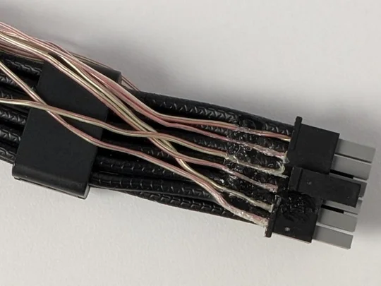
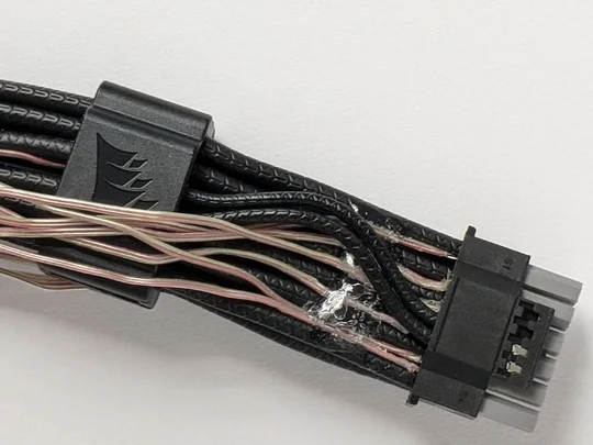
Au cours du développement, des sondes thermiques ont été fixées aux bornes à l'intérieur du connecteur afin de mesurer leur température et de déterminer la valeur appropriée du thermocontact.
La gaine en PVC qui entoure chaque fil constitue un excellent isolant électrique et thermique. Cela est particulièrement vrai par rapport au cuivre qu’elle renferme. Cette différence fait de l’isolant une barrière thermique efficace, réduisant les pertes de chaleur radiales des conducteurs en cuivre vers l’environnement. C’est pourquoi il est inefficace de mesurer les températures à l’aide d’un thermomètre infrarouge. Les pertes par convection et par rayonnement étant maîtrisées, le différentiel thermique (ΔT) entre les fils de cuivre est mieux préservé, ce qui permet à la chaleur produite au niveau du connecteur 12 V-2x6 de se propager longitudinalement à travers le cuivre et d'atteindre l'endroit où nous la mesurons (le peigne, à 30 mm de distance) pratiquement intacte. La température de déclenchement de l'interrupteur, fixée à 65 °C, a été choisie en tenant compte de ce gradient : une lecture de 65 °C au niveau du peigne correspond à une extrémité du connecteur nettement plus chaude, et le seuil de 65 °C a été validé comme représentant une condition nécessitant véritablement une intervention.
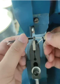
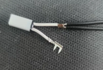
Chaque câble est assemblé à la main. Sur les photos ci-dessus, à gauche, les deux fils de détection sont en train d'être sertis sur l'interrupteur bimétallique. À droite, on peut voir l'interrupteur avec les deux fils de détection et les dérivations qui traversent l'isolation du câble et relient l'interrupteur aux fils de masse du câble 12 V-2x6.
L'Assemblée
Le module ThermalProtect intégré au peigne de câbles se compose de cinq éléments :
1 : Interrupteur thermique : un interrupteur bimétallique normalement fermé, conçu pour s'ouvrir à 65 °C ± 5 °C. Le terme « bimétallique » désigne deux métaux assemblés qui présentent des coefficients de dilatation thermique différents. Lorsque la température atteint un certain seuil, la dilatation différentielle provoque l'ouverture physique des contacts. Aucune alimentation n'est nécessaire, aucun traitement du signal n'est requis, et aucun micrologiciel n'est utilisé. Il s'agit du même mécanisme de base qu'un disjoncteur, mais à commande thermique.
2 : Cale en cuivre : fine cale en cuivre qui s'enroule autour du thermocontact et sert d'interface thermique. Elle comble l'espace entre la surface du fil et le corps du thermocontact et réduit au minimum la résistance de contact dans le circuit thermique. Il est essentiel que cette pièce soit bien ajustée : une interface thermique défaillante à cet endroit entraînerait un décalage entre la température du thermocontact et celle du fil, ce qui réduirait la vitesse et la précision de la réponse.
Ensemble de peigne
3 : Couvercle supérieur : maintient l'ensemble en place et protège l'interrupteur contre les chocs liés à la manipulation ou à la flexion des câbles.
4 : Cadre central : il positionne et maintient l'ensemble de commutateurs revêtu de cuivre contre les fils appropriés (les fils d'alimentation, et non les fils de signal) et assure une pression de contact mécanique constante.
5 : Couvercle inférieur : la base structurelle qui assure l'alignement de l'ensemble sur le faisceau de câbles.
Illustration montrant le câblage du thermocontact. Ce dernier est entouré d'une agrafe en cuivre et se trouve entre les câbles à l'intérieur du produit.
Le thermocontacteur est câblé en série avec les fils de signal S4 (Sense1) et S3 (Sense0) du connecteur 12V-2x6. En fonctionnement normal, le thermocontacteur est fermé ; S3 et S4 sont donc reliés à la masse via le thermocontacteur, et le GPU interprète cela comme une autorisation de puissance de 600 W. Le commutateur est orienté, côté non marqué, vers les fils d'alimentation +12 V, car ce sont ces fils qui transportent le courant le plus intense et qui seront les premiers à chauffer en cas de défaillance.
Dans un environnement à 60 °C, nous avons testé une GeForce RTX 5090 en laissant volontairement un espace de 3 mm au niveau du connecteur 12 V (2x6). En moins d'une minute et 20 secondes, alors que la température au niveau du connecteur dépassait les 115 °C, le système ThermalProtect s'est déclenché et le GPU s'est arrêté. À ce stade, le connecteur a immédiatement commencé à refroidir.
Lorsque le disjoncteur thermique de ThermalProtect s'ouvre sous l'effet de la chaleur, les broches S3 et S4 perdent leur connexion à la masse. Le GPU détecte cela et en conclut immédiatement que l'alimentation fournie par le câble 12V-2x6 provenant du bloc d'alimentation est insuffisante. Cela provoque l'arrêt du GPU.
Ce que l'on voit quand il se déclenche
Lorsque ThermalProtect s'active, le GPU réduit sa puissance maximale et votre écran devient noir. Il ne s'agit pas d'un plantage du système, car le reste de l'ordinateur continue de fonctionner. Les ventilateurs tournent toujours, les lumières RGB sont toujours allumées et le système d'exploitation ne s'est pas bloqué. Cela ressemble à une déconnexion de l'écran, car c'est effectivement ce qui s'est produit : le GPU a cessé d'afficher l'image.
Si vous voyez ce message, ne pensez pas tout de suite que le connecteur est en feu. L'intérêt de ThermalProtect, c'est justement de détecter le problème avant que la situation n'en arrive là. Voici ce que vous devez faire :
- Maintenez le bouton d'alimentation enfoncé jusqu'à ce que le système s'éteigne – maintenez-le enfoncé pendant deux à trois secondes. Éteignez ensuite le bloc d'alimentation à l'aide de l'interrupteur situé à l'arrière, puis débranchez-le de la prise murale.
- Laissez le câble refroidir. Placez le dos de votre main près du câble (sans le toucher), du côté du GPU. Si vous sentez de la chaleur à environ 2,5 cm de distance, attendez. Laissez-le refroidir pendant au moins 20 minutes avec le panneau latéral ouvert.
- Une fois qu'il a refroidi, débranchez le câble 12 V (2 x 6) du GPU et du bloc d'alimentation, puis examinez les deux extrémités. Vérifiez s'il y a des traces de décoloration, de plastique fondu ou de broches déformées. Si vous constatez l'un de ces problèmes, ne réutilisez pas le câble.
- Si tout semble en ordre, réinstallez le câble. Enfoncez fermement le connecteur jusqu’à ce que vous entendiez le clic du loquet de verrouillage. Vérifiez ensuite visuellement : aucune partie grise ne doit être visible à l’extrémité du connecteur. Si du gris est visible, cela signifie qu’il n’est pas correctement enclenché. Une lampe de poche peut vous aider dans cette opération.
- Rebranchez le bloc d'alimentation de la même manière, remettez le courant, et le tour est joué.
Astuce : si vous avez des données non enregistrées, vous pourrez peut-être y accéder en branchant le câble d'affichage directement sur votre carte mère (à condition que celle-ci dispose d'une sortie vidéo et que votre processeur intègre un processeur graphique).
Pourquoi la protection passive est la bonne solution
Il existe d'autres façons d'aborder la protection thermique d'un câble. On pourrait installer un capteur de température sur le câble et le relier à un microcontrôleur qui communiquerait avec le GPU via un bus de communication. On pourrait intégrer une thermistance NTC et en lire les valeurs à l'aide d'un logiciel. On pourrait également se connecter aux systèmes de protection du bloc d'alimentation.
Chacune de ces approches introduit des dépendances dont un interrupteur bimétallique est dépourvu. Une solution active a besoin d'alimentation pour fonctionner. Elle nécessite un micrologiciel ou un logiciel, ce qui signifie qu'elle peut comporter des bogues, et ces bogues peuvent l'empêcher de vous protéger au moment le plus critique ou la faire se déclencher alors qu'elle ne le devrait pas. Elle peut nécessiter un bloc d'alimentation ou un processeur graphique spécifique pour fonctionner. Elle peut utiliser des composants qui ne permettent pas de mesurer la température de conducteurs sous tension et doivent donc mesurer les fils de terre (comme c'est le cas avec les thermistances NTC).
Depuis des décennies, le thermocontacteur bimétallique remplit sa fonction de manière fiable dans les disjoncteurs, les appareils électroménagers et les équipements industriels. Il ne dispose ni de micrologiciel, ni de source d'alimentation. Il réagit à la température, car c'est précisément celle-ci qui provoque la déformation du métal. Son mode de défaillance est bien connu et sa durée de vie nominale s'élève à plusieurs dizaines de milliers de cycles.
Grâce à cette approche passive, ThermalProtect fonctionne quel que soit le bloc d'alimentation utilisé ou le fabricant de votre carte graphique. Il suffit que les deux extrémités soient équipées d'un connecteur 12 V 2x6 natif, ce qui est le cas de toute implémentation conforme. ThermalProtect fonctionne. Sans exception, sans réserve, et sans qu'il soit nécessaire de consulter une liste de compatibilité autre que la norme du connecteur elle-même.
Un câble ThermalProtect en cours de test sur une carte 5090 dans notre laboratoire de Milpitas.
Caractéristiques techniques du câble
Caractéristiques électriques et physiques
|
Paramètre |
Spécifications |
|
Norme relative aux connecteurs d'alimentation |
PCIe 5.1 / 12 V - 2 x 6 |
|
Puissance nominale maximale |
600 W |
|
Longueur du câble |
650 mm ± 10 mm |
|
Section des câbles électriques |
16 AWG (0,1 mm × 165 conducteurs) |
|
Section des fils de signal (broches de détection) |
24 AWG (0,16 mm × 11 conducteurs) |
|
Fil de signal du thermocontact |
26 AWG UL3266, résistance thermique de 125 °C |
|
Norme relative à l'isolation des fils |
UL 1569, classé 105 °C VW-1 |
|
Boîtier de connecteur |
12+4 H++ (Noir / Gris froid 8C), UL 94V-0 |
|
Bornes d'alimentation |
Alliage de cuivre, 12 broches, géométrie des contacts à 3 alvéoles |
|
Terminaux de détection |
Bronze phosphoreux, 4 pôles, géométrie de contact à 3 alvéoles |
|
Conformité RoHS |
Conforme à la directive européenne 2011/65 |
Module ThermalProtect
|
Paramètre |
Spécifications |
|
Type de commutateur |
Interrupteur thermique bimétallique, normalement fermé |
|
Température de voyage |
65 °C ± 5 °C |
|
Réinitialisation automatique |
Oui — se réinitialise automatiquement une fois refroidi |
|
Voie de détection |
Pince en cuivre, contact direct avec les fils d'alimentation de calibre 16 |
|
Positionnement du peigne |
à 30 mm du connecteur côté GPU |
|
Commande par broche de détection |
S3 et S4 (Sense0, Sense1) |
|
État normal |
S3 et S4 reliés à la masse — 600 W disponibles |
|
État déclenché |
S3 et S4 activés — Puissance maximale du GPU limitée à 150 W |
|
Électronique active |
Aucun |
Brevet
ThermalProtect est une technologie en instance de brevet. Le brevet porte sur l'intégration d'un interrupteur thermique passif dans un faisceau de câbles 12 V-2x6, de manière à utiliser les conducteurs en cuivre du câble comme voie de détection thermique – plus précisément, l'utilisation d'une interface thermique en cuivre pour coupler l'interrupteur aux fils d'alimentation, et l'intégration de cet interrupteur dans le circuit de broches de détection 12 V-2x6 afin de contrôler la réduction de la charge du GPU.
Compatibilité
Compatible avec :
- Tout GPU équipé d'un connecteur d'alimentation natif 12 V (2 x 6 broches)
- Tout bloc d'alimentation doté d'une sortie native 12 V (2 x 6 A) – quelle que soit la marque ou la puissance
- Prises 12VHPWR (géométrie du boîtier identique)
- CORSAIR : RM750x, RM850x, RM1000x (2024 et après), RM750e/850e/1000e/650e (2025), RM850x/1000x SHIFT (2025), HX1000i/1200i/1500i SHIFT, WS3000, CX750M/CX650M (2025)
Ne fonctionne pas avec :
- Configurations des adaptateurs – Les adaptateurs 2x8 broches vers 12 V-2x6 placent la jonction hors du champ de détection du capteur. Des versions ThermalProtect pour les sorties des blocs d'alimentation CORSAIR de type 4 et de type 5 sont en cours de développement.
- Connecteurs d'alimentation GPU traditionnels à 6 ou 8 broches – une interface physique totalement différente.
Foire aux questions
ThermalProtect nécessite-t-il un logiciel, des pilotes ou un micrologiciel ?
Non. Il s'agit d'un interrupteur mécanique relié à une broche de signal. Il n'y a rien à installer, rien à mettre à jour, rien à configurer.
Est-ce que ça va planter pendant une partie normale ?
Non, pas si le connecteur est correctement enfoncé. Dans des conditions normales – connecteur entièrement inséré, câble acheminé sans tension excessive, circulation d'air suffisante dans le boîtier –, la température du câble ne s'approchera pas des 65 °C. Le système ThermalProtect est conçu pour les situations de défaillance, et non pour un fonctionnement normal.
Si le disjoncteur se déclenche, est-ce que quelque chose a été endommagé ?
C'est justement ce que ce système est censé empêcher. Si ThermalProtect s'est déclenché, cela signifie qu'il a détecté le problème avant que des dommages thermiques ne se produisent. Suivez la procédure de réinitialisation, vérifiez que le connecteur est bien enfoncé, et dans la plupart des cas, tout devrait rentrer dans l'ordre. Si vous constatez une décoloration ou du plastique fondu lors de l'inspection, c'est une autre histoire. Cela signifie que le problème était déjà bien avancé avant que le système de protection ne se déclenche, et le câble doit être remplacé.
La marque de l'alimentation électrique a-t-elle de l'importance ?
Pas du tout. ThermalProtect fonctionne via le protocole standard 12 V-2x6 pour les broches de détection, que tous les GPU compatibles prennent en charge. Il ne communique en aucune façon avec le bloc d'alimentation. Ce dernier sert simplement de source d'alimentation.
L'interrupteur peut-il s'user à force d'être actionné ?
Les interrupteurs bimétalliques, comme celui utilisé ici, sont conçus pour supporter plusieurs milliers de cycles. L'interrupteur lui-même ne s'use pratiquement pas. Cela dit, si le ThermalProtect se déclenche à plusieurs reprises, la solution n'est pas d'ignorer l'interrupteur, mais de réparer ce qui provoque la surchauffe du connecteur.
Puis-je modifier le seuil de 65 °C ?
Non. Il s'agit d'un composant mécanique à déclenchement fixe, conçu pour offrir une marge de sécurité suffisante au-delà des températures normales de fonctionnement, tout en se déclenchant bien avant que le câble ou le connecteur ne soit endommagé. Il n'est pas réglable sur site.
Puis-je inverser le câble pour que l'interrupteur se trouve du côté du bloc d'alimentation ?
Non, l'extrémité du câble équipée du module/peigne ThermalProtect doit toujours être branchée sur la carte graphique ; elle est étiquetée pour éviter toute confusion.
Puis-je plier le câble entre le connecteur 12 V-2x6 et l'interrupteur ThermalProtect ?
Oui, le câble est fixé dans le peigne, ce qui rend la manipulation moins aisée qu'avec d'autres câbles, mais il est conçu pour pouvoir être plié à 90 degrés à cet endroit si nécessaire.
En résumé
Le connecteur 12 V-2x6 a permis de résoudre le problème de gestion des câbles multiples et a ensuite contribué à réduire le risque d'incendie lié à une insertion partielle. Ce qu'il ne pouvait toutefois pas faire à lui seul, c'était assurer une protection continue une fois le câble sorti de l'usine. Il n'y a aucun moyen de savoir si un connecteur s'est desserré de lui-même six mois après son installation.
ThermalProtect comble cette lacune grâce à un interrupteur thermique passif qui surveille le câble en permanence, réagit lorsque la température augmente et fonctionne avec tout matériel compatible avec la norme 12V-2x6. Il n'ajoute pas de complexité. Il apporte une protection supplémentaire.
Le cuivre qui conduit le courant est le même que celui qui transmet la chaleur au capteur. Ce n'est pas un hasard. C'est voulu.
PRODUITS DANS L'ARTICLE
Stay up to date with CORSAIR. Get our latest News, Guides, and Product Updates in your Google feeds.
Add CORSAIR as a preferred source
JOIN OUR OFFICIAL CORSAIR COMMUNITIES
Join our official CORSAIR Communities! Whether you're new or old to PC Building, have questions about our products, or want to chat about the latest PC, tech, and gaming trends, our community is the place for you.