MANUAL | QUICK START GUIDE
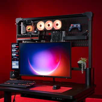
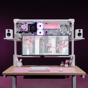
MULTI FRAME PEGBOARD
CLAMP-ON DESK ORGANIZER
In this Guide
BEFORE YOU START
Congratulations on purchasing your new CORSAIR Multi Frame Pegboard.
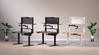
There are multiple versions of the Multi Frame Pegboard, for different sized desks. Some images may show products that are a different size than the product you have, but the installation method is identical unless noted otherwise. Please take a moment to carefully read this guide prior to assembling.
MULTI FRAME PEGBOARD - PARTS LIST
LARGE ITEMS LIST
* Not available on some models
Pegboards (2x)
Main T-Channel Rail (1x)
Top T-Channel Rail (1x)
Vertical T-Channel Rails (2x)
Bottom Brace (1x)
Large Shelf (1x)
Small Shelves (2x)
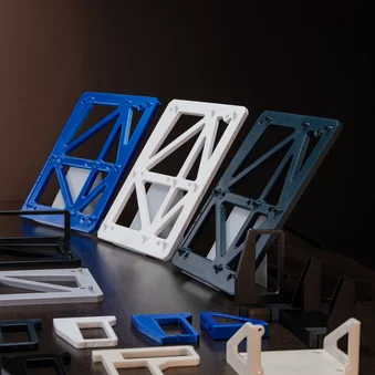
Right and Left Corner Supports
(1x each)
SMALL ITEMS LIST
* Not available on some models
M8 16mm Flathead Bolts (5x)
M8 12mm Bolts (5x)
M6 10mm Bolts (26x)
M6 15mm Bolts (8x)
Pegboard Push Button Mounts (9x)
M6 Black T-Nuts (6x)
1/4" 20 Silver T-Nuts (6x)
Right and Left Corner Support Clamps (1x each)
Short Pegboard Hooks (3x)
Long Pegboard Hooks (3x)
L-Shaped Pegboard Hooks (4x)
Wide Pegboard Hooks (2x)
Pegboard Multi-hook (1x)
Straight Cable Channels (2x)
Curved Cable Channels (2x)
Corner Covers (2x)
Small Wire Management Tray (1x)
Elgato Flex Arm Adapters (2x)
Buckle Velcro Ties (10x)
Zip Ties (10x)
3mm Hex Tool (1x)
5mm Hex Tool (1x)
HARDWARE BAGS
STEP 1 AND 2
M6 10mm Bolts (6x)
STEP 3 AND 4
M8 16mm Flathead Bolts (4x)
M8 12mm Bolts (4x)
STEP 14
M6 10mm Bolts (6x)
STEP 15
M6 15mm Bolts (4x)
ELGATO ADAPTER
Elgato Flex Arm Adapters (2x)
T-NUTS
M6 Black T-Nuts (6x)
M6 Black T-Nut Set Screws (6x)
T-NUTS
1/4" 20 Silver T-Nuts (6x)
1/4" 20 Silver T-Nut Set Screws (6x)
SPARE PARTS AND TOOLS
M6 Black T-Nuts Set Screws (2x)
1/4 20 Silver T-Nut Set Screw (1x)
M6 15mm Bolts (4x)
M6 10mm Bolts (14x)
M8 12mm Bolt (1x)
M8 16mm Flathead Bolt (1x)
Pegboard Push Button Mounts (9x)
5mm Hex Tool (1x)
3mm Hex Tool (1x)
1/8 Hex Tool (1x)
ASSEMBLING THE MULTI FRAME PEGBOARD
1: INSERTING THE T-CHANNEL RAILS
To complete the step, the following hardware will be used:
Right and Left Corner Supports
(1x each)
Vertical T-Channel Rails (2x)
- Insert the Vertical T-Channel Rails (4) into the top openings on the Right and Left Corner Supports (8). Ensure the T-Nuts in the T-Channel Rails (4) face the rear of the desk.
2: SECURING THE T-CHANNEL RAILS TO THE CORNER SUPPORTS
To complete the step, the following hardware and tool will be used:
M6 10mm Bolts (6x)
5mm Hex Tool (1x)
- Secure each Vertical T-Channel Rail (4) to each Corner Support (8) by screwing in three M6 10mm Bolts (B), ensuring the base is flush.
3: INSTALLING THE CLAMPS TO THE VERTICAL T-CHANNEL RAILS
To complete the step, the following hardware and tool will be used:
M8 16mm Flathead Bolts (4x)
5mm Hex Tool (1x)
- Secure the Right Corner Support Clamp (F) head to the bottom of the Vertical T-Channel Rail (4) and Right Corner Support (8) assembly by screwing in two M8 16mm Flathead Bolts (A1).
- Secure the Left Corner Support Clamp (F) head to the bottom of the Vertical T-Channel Rail (4) and Left Corner Support (8) assembly by screwing in two M8 16mm Flathead Bolts (A1).
4: ASSEMBLING THE CORNER SUPPORT CLAMPS
To complete the step, the following hardware and tool will be used:
M8 12mm Bolts (4x)
5mm Hex Tool (1x)
- Assemble each of the Corner Support Clamps (F) by attaching the bottom part of the clamp to the base and screwing in two M8 12mm Bolts (A2).
5: ATTACHING THE CORNER SUPPORT CLAMPS TO THE DESK
- Attach the Right Corner Support Clamp (F) to the desired location on your desk and rotate the tightening screw clockwise until secure.
6: FITTING THE MAIN T-CHANNEL RAIL TO THE RIGHT CORNER SUPPORT
To complete the step, the following hardware will be used:
Main T-Channel Rail (1x)
- Once you have fully secured the Right Corner Support (8), slide the Main T-Channel Rail (2) over the horizontal T-Nuts. Do not tighten the T-Nut set screws yet.
7: FITTING THE LEFT CORNER SUPPORT AND SECURING THE ASSEMBLY
- Align the Left Corner Support (8) to the Main T-Channel Rail (2) by sliding the rail over the horizontal T-Nuts in the support.
- Secure the Left Corner Support Clamp (F) to the desk by rotating the tightening screw clockwise.
8: SECURING THE MAIN T-CHANNEL RAIL
To complete the step, the following tool will be used:
3mm Hex Tool (1x)
- Using the 3mm Hex Tool (W), secure the Main T-Channel Rail (2) by tightening all four horizontal T-Nuts on the Corner Supports (8).
9: REMOVING THE CORNER SUPPORT COVERS (PLATFORM DESK ONLY)
- Remove the covers from both Corner Supports (8) by gently prying them off with a flat screwdriver like shown on the image below.
10: INSERTING THE T-CHANNEL RAILS (PLATFORM DESK ONLY)
To complete the step, the following hardware will be used:
Vertical T-Channel Rails (2x)
M6 10mm Bolts (4x)
- Insert the Vertical T-Channel Rails (4) into the top openings on the Right and Left Corner Supports (8). Ensure the T-Nuts in the T-Channel Rails (4) face the rear of the desk.
- Secure each Vertical T-Channel Rail (4) to each Corner Support (8) by screwing in two M6 10mm Bolts (B).
11: INSTALLING THE TOP RAIL
To complete the step, the following hardware and tools will be used:
Top T-Channel Rail (1x)
M6 15mm Bolts (4x)
3mm Hex Tool (1x)
5mm Hex Tool (1x)
- If the M6 15mm Bolts (C) are not pre-installed in the rear of your Top T-Channel Rail (3), install them in the T-Nuts like shown on the image below. Tighten the bolts only halfway.
- Attach the Top T-Channel Rail (3) by sliding its 90° T-Nuts into the vertical channels of the Vertical T-Channel Rails (4). Ensure the bolts in the Top T-Channel Rail (3) are facing the rear of the desk.
- Tighten the set screws of all four 90° T-Nuts.
12: ATTACHING THE CORNER COVERS
To complete the step, the following hardware will be used:
Corner Covers (2x)
- Push the Corner Covers (M) over the top corners of the T-Channel Rail assembly until they snap into place.
13: HANGING THE PEGBOARDS
To complete the step, the following hardware will be used:
Pegboards (2x)
- Hook the Pegboards (1) onto the four bolts in the rear of the Top T-Channel Rail (3).
14: SECURING THE PEGBOARDS
To complete the step, the following hardware and tool will be used:
M6 10mm Bolts (6x)
5mm Hex Tool (1x)
There are two T-Nuts pre-installed in the rear of the Top T-Channel Rail (3) and two in the rear of each Vertical T-Channel Rail (4).
- Secure the Pegboards (1) onto the pre-installed T-Nuts by screwing in six M6 10mm Bolts (B) like shown in the image below.
15: ATTACHING THE BOTTOM BRACE
To complete the step, the following hardware and tool will be used:
Bottom Brace (1x)
M6 15mm Bolts (4x)
5mm Hex Tool (1x)
- Secure the Pegboards (1) with the Bottom Brace (5) and four M6 15mm Bolts (C).
16: ATTACHING THE PEGBOARD HOOKS
To complete the step, the following hardware will be used:
Short Pegboard Hooks (3x)
Long Pegboard Hooks (3x)
L-Shaped Pegboard Hooks (4x)
Wide Pegboard Hooks (2x)
Pegboard Multi-hook (1x)
- Mount the hooks onto the Pegboard (1) by inserting them through the holes. You can use any position on the Pegboard (1).
17: USING T-NUTS TO INSTALL ACCESSORIES
T-Nuts allow you to add accessories and extensions to the Platform's rail system. The black T-Nuts are M6 threaded and used for assembly of extensions and accessories. The silver T-Nuts are quarter-inch threaded and are compatible with Elgato mount products.
To add and secure a T-Nut to a rail, follow the next steps:
1. Rotate the T-Nut horizontally.
2. Slide the T-Nut into the rail sideways.
3. Once the T-Nut is in the slot, rotate it back to its correct orientation.
4. Using a 3mm Hex Tool (W), tighten the set screw inside the T-Nut to secure it in place.
18: MOUNTING THE SHELVES
To complete the step, the following hardware and tools will be used:
Large Shelf (1x)
Small Shelves (2x)
M6 10mm Bolts (6x)
M6 Black T-Nuts (6x)
3mm Hex Tool (1x)
5mm Hex Tool (1x)
LARGE SHELF
- Insert two M6 Black T-Nuts (E1) into the front side of the Top T-Channel Rail (3) and slide them into place where you want to install the shelf.
- Align the T-Nuts (E1) with the holes in the Large Shelf (6) mounting bracket.
- Secure the Large Shelf (6) by screwing in two M6 10mm Bolts (B).
SMALL SHELVES
- Insert two M6 Black T-Nuts (E1) into each of the two channels on the sides of the Vertical T-Channel Rail (4) and slide them into place where you want to install the shelves.
- Align the T-Nuts (E1) with the holes in the Small Shelf (7) mounting bracket and tighten the set screws in the T-Nuts (E1).
- Secure the Small Shelf (7) by screwing in two M6 10mm Bolts (B).
- Repeat the process on the opposite side.
19: CABLE MANAGEMENT
Behind the Pegboard, you can install cable trays and cabling if you are using Elgato Key Lights or other devices mounted to the Multi Frame system. These can be mounted to the Pegboards using the included Pegboard Push Button Mounts or to the T-Channel Rails using the T-Nuts.
To complete the step, the following hardware and tools will be used:
Pegboard Push Button Mounts (9x)
Straight Cable Channels (2x)
Curved Cable Channels (2x)
Buckle Velcro Ties (6x)
Zip Ties (6x)
COMBINING THE CABLE CHANNELS
Straight (L1) and Curved Channels (L2) can snap together to help you route and conceal cables.
ATTACHING THE CABLE CHANNELS TO THE PEGBOARD
- Align the mounting holes of the Cable Channels (L1 or L2) to the holes in the Pegboard (1).
- Secure the Channels to the Pegboard by pushing two Pegboard Push Button Mounts (D) through its mounting holes until they snap into place.
ATTACHING THE CABLE CHANNELS TO THE T-CHANNEL RAIL (OPTIONAL)
- Insert two M6 Black T-Nuts (E1) into the back of the Top T-Channel Rail (3). Do not tighten the set screws yet.
- Align the mounting holes of the Straight Cable Channel (L1) with the holes in the M6 Black T-Nuts (E1).
- Tighten the set screws if you do not wish the Cable Channels (L1 and L2) to slide freely along the T-Channel Rail (2).
- Secure the Straight Channel (L1) to the M6 Black T-Nuts (E1) by screwing in two M6 10mm Bolts (B).
SECURING THE CABLES TO THE CABLE CHANNELS
- Secure the cables by threading the included Buckle Velcro Ties (T) or Zip Ties (U) through the gaps in the channels.
ADDITIONAL FEATURES
The Multi Frame Pegboard includes useful additional features enabled by optional accessories. To browse compatible products (sold separately), please visit www.elgato.com.
To mount the Elgato Flex Arm Adapter, use the following hardware:
Elgato Flex Arm Adapters (2x)
1/4" 20 Silver T-Nuts (2x)
3mm Hex Tool (1x)
- Insert a 1/4" 20 Silver T-Nut to the Main T-Channel Rail (2) or Top T-Channel Rail (3).
- Mount the Elgato Flex Arm Adapter (O) by screwing it into the 1/4" 20 Silver T-Nuts (E2).
WARRANTY

CORSAIR Multi Frame Pegboards have a 5-year warranty.
LEGAL
©2025 CORSAIR MEMORY, Inc. Trademarks belong to their respective owners. All rights reserved.
RELATED CONTENT