- SPECIFICHE DEL CASE
- CONTENUTO DEL KIT ACCESSORI
- CASE EXPANDED VIEWS
- INSTALLAZIONE / RIMOZIONE DEL PANNELLO
- INSTALLAZIONE DELLA SCHEDA MADRE
- INSTALLAZIONE DEI CAVI I/O ANTERIORI
- INSTALLAZIONE DELLA BANDA MAGNETICA
- INSTALLAZIONE DEL VENTILATORE
- SUPPORTO DI RAFFREDDAMENTO PERSONALIZZATO HYDRO X
- INSTALLAZIONE DEL RADIATORE
- INSTALLAZIONE DI DISPOSITIVI DI MEMORIA E CONTROLLER
- INSTALLAZIONE DELL'ALIMENTATORE
- INSTALLAZIONE DELLA SCHEDA GRAFICA
- CONNETTERE I TUOI FAN
- MANUTENZIONE
- CERTIFICAZIONE DI GARANZIA
- PRODUCT CHANGES
- AVAILABLE ACCESORIES
- SPARE PARTS LISTING
- LEGAL
- CONTENUTI CORRELATI
MANUALE | GUIDA RAPIDA
Serie CORSAIR FRAME 4000
MODULAR MID-TOWER CASE
La versione inglese è disponibile qui - English
Se avete altri problemi contattateci assistenza clienti
SPECIFICHE DEL CASE
|
Configurazione slot PCI |
7 Orizzontale / 3 Verticale |
|
Compatibilità della scheda madre |
Mini-ITX, Micro-ATX, ATX, E-ATX (305 mm x 277 mm) |
|
HDD |
|
|
SSD |
|
|
Colori disponibili |
|
|
Materiale del pannello laterale sinistro |
Vetro temperato |
|
Materiale del pannello frontale |
|
|
Spazio cavo posteriore |
37 mm |
|
Filtri antipolvere |
Front, Side, Bottom |
|
I/O anteriore |
Standard FPIO (FRAME 4000D, FRAME 4000D WOOD, FRAME 4000X):
ELITE FPIO (FRAME 4000D LCD, FRAME 4000D Vault SERIES):
|
1. POSIZIONE DELLE VENTOLE
NOTE: No fans are included with the FRAME 4000D or FRAME 4000D Vault Series.
| FRAME 4000D RS/RS ARGB | ||||||
|
Fronte |
Inizio pagina |
Posteriore |
Lato |
Copertura PSU | Bottom | |
|
3x 120 mm 2x 140 mm 2x 200 mm |
3x 120 mm 2x 140 mm
|
1x 120 mm 1x 140 mm
|
3x 120 mm 2x 140 mm
|
2x 120 mm |
None |
|
|
FRAME 4000D LCD, FRAME 4000D WOOD, FRAME 4000X |
||||||
|
Front |
Top |
Rear |
Side |
PSU Shroud | Bottom | |
|
3x 120mm 2x 140mm 2x 200mm |
3x 120mm 2x 140mm
|
1x 120mm 1x 140mm
|
3x 120mm 2x 140mm
|
2x 120mm |
1x 120mm |
|
2. VENTILATORI E CONTROLLER INCLUSI
|
TELAIO 4000D |
TELAIO 4000D RS | TELAIO 4000D RS ARGB |
FRAME 4000D WOOD, FRAME 4000X |
FRAME 4000 LCD
|
|
|
Nessuno |
3x RS120 (Pre-installed) |
3x RS120 ARGB (Pre-installed) |
4x RS120 (Pre-installed) |
4x RS120 ARGB (Pre-installed) |
|
NOTE: Fans and lighting controllers are not included. ARGB lighting can be controlled through your motherboard or with a separate fan controller.
3. COMPATIBILITÀ DEL RADIATORE
|
Fronte |
Inizio pagina |
Posteriore |
Lato |
Copertura PSU |
|
240 mm 280 mm 360 mm |
240 mm 280 mm 360 mm |
120 mm 140 mm |
240 mm 280 mm 360 mm |
Nessuno |
4. DIMENSIONI DELLA VALIGETTA
| Dimensioni |
487 mm x 239 mm x 486 mm |
|
Lunghezza massima GPU |
430 mm |
|
Altezza massima del dispositivo di raffreddamento della CPU |
170 mm |
|
Lunghezza massima della PSU |
220 mm |
CONTENUTO DEL KIT ACCESSORI
1x Staffa di montaggio per ventola laterale
1x Connettore inverso con striscia magnetica
12x InfiniRail Fan Mounts
(Pre-Installed on Select Cases)
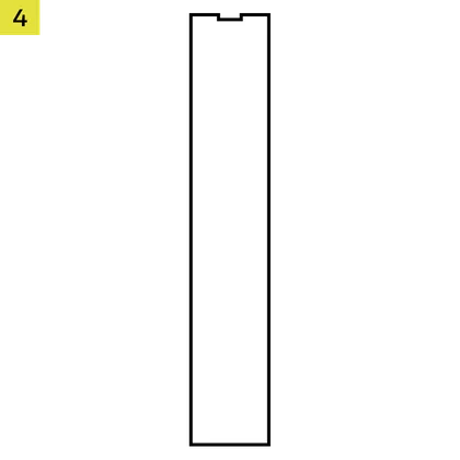
1x Solid Side Insert
(Select Models)

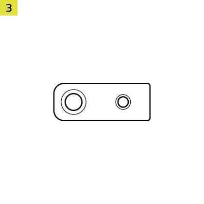
1x GPU Anti-sag Stabilization Arm Mini Mount
1x GPU Anti-sag Stabilization Arm Rubber Spacer
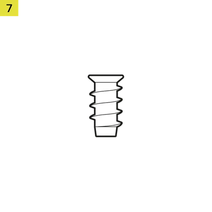
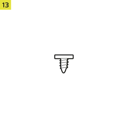
12-28x Self-Tapping Fan Screws
(Qty varies by model)
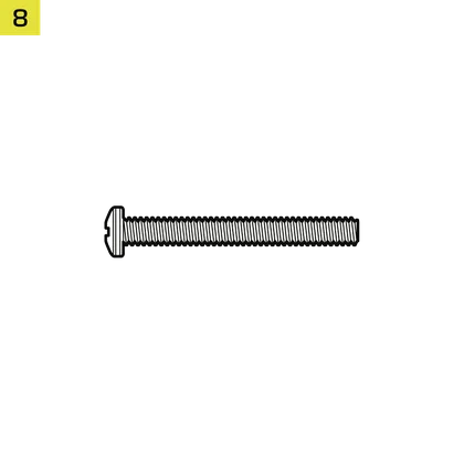
8-12x Long Fan Screws (6-32 UNC; 30mm)
(Qty varies by model)
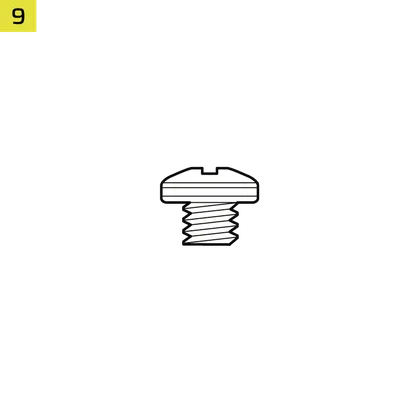
18 viti per scheda madre/HDD (6-32 UNC; 6 mm)

8-16x SSD Screws (M3 x 0.5; 5mm)
(Qty varies by model)
1x Distanziale di ricambio per scheda madre

2 distanziatori per montaggio verticale
InfiniRail Fan Mount Lock Screws
(Pre-Installed on Select Models)
1 cavo adattatore I/O frontale
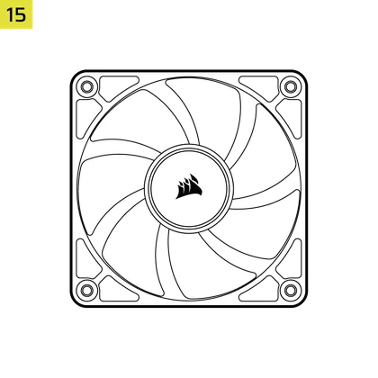
3x or 4x RS120 / RS 120 ARGB Fans
(Pre-Installed on Select Models)
12x QuikTurn® Fan Screws
(Select Models)

CASE EXPANDED VIEWS
FRAME 4000D RS/RS ARGB
| A. Pannello laterale in vetro a tre quarti | H. Filtro della ventola laterale |
| B. Piastra PCI | I. Pannello frontale |
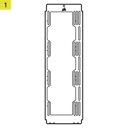
| C. Vassoio standard in acciaio per scheda madre | J. Filtro della ventola anteriore |
| D. Pannello superiore | K. Filtro della ventola PSU |
| E. Piastra drive / controller | L. Copertura PSU |
| F. Cable Shroud with GPU Anti-sag Stabilization Arm | M. Inserto laterale traslucido |
| G. Pannello laterale in acciaio | N. Quarto di pannello laterale in mesh |
FRAME 4000D LCD
| B. PCI Plate | J. Front Fan Filter |
| C. Standard Steel Motherboard Tray | K. PSU Fan Filter |
| D. Top Panel | O. Front Panel I/O |
| E. Drive / Controller Plate | P. Compact PSU Shroud |
| F. Cable Shroud with GPU Anti-sag Stabilization Arm | Q. Two-Thirds Side Glass Panel |
| G. Steel Side Panel | R. LCD Screen Mounting Bracket |
| H. Side Fan Filter | S. XENEON EDGE LCD Touchscreen |
| I. Front Panel |
FRAME 4000X
| B. PCI Plate | J. Front Fan Filter |
| C. Standard Steel Motherboard Tray | K. PSU Fan Filter |
| D. Top Panel | O. Front Panel I/O |
| E. Drive / Controller Plate | P. Compact PSU Shroud |
| F. Cable Shroud with GPU Anti-sag Stabilization Arm | T. RGB FLOW Front Panel |
| G. Steel Side Panel | U. Full Tempeed Side Glass Panel |
| H. Side Fan Filter |
FRAME 4000D WOOD
| B. PCI Plate | J. Front Fan Filter |
| C. Standard Steel Motherboard Tray | K. PSU Fan Filter |
| D. Top Panel | O. Front Panel I/O |
| E. Drive / Controller Plate | P. Compact PSU Shroud |
| F. Cable Shroud with GPU Anti-sag Stabilization Arm | U. Full Tempered Glass Side Panel |
| G. Steel Side Panel | V. Wood Front Panel |
| H. Side Fan Filter |
FRAME 4000D Vault Series
| B. PCI Plate | I. Front Panel |
| C. Standard Steel Motherboard Tray | J. Front Fan Filter |
| D. Top Panel | K. PSU Fan Filter |
| E. Drive / Controller Plate | O. Front Panel I/O |
| F. Cable Shroud with GPU Anti-sag Stabilization Arm | P. Compact PSU Shroud |
| G. Steel Side Panel | U. Full Tempered Side Glass Panel |
| H. Side Fan Filter |
INSTALLAZIONE / RIMOZIONE DEL PANNELLO
ATTENZIONE: questo prodotto contiene vetro temperato. Maneggiare con cura.
- Per evitare danni o lesioni, evitare di posizionare o riporre la custodia su superfici dure come piastrelle in ceramica o porcellana, pietra, muratura o cemento.
- CORSAIR raccomanda vivamente di rimuovere tutti i pannelli laterali in vetro temperato prima di posizionare il case o iniziare l'assemblaggio su una superficie rigida.
- Se è necessario posizionare la struttura finita su una superficie dura, sollevare o isolare il case per ridurre al minimo il rischio di contatto accidentale, danni o lesioni personali.
I pannelli di ricambio sono disponibili all'indirizzo www.corsair.com. Per assistenza, contattare help.corsair.com.
1. RIMOZIONE DEI PANNELLI LATERALI
NOTE: This case is available with different left side panel designs (full glass or split glass/steel). Depending on your model, you may have one or multiple panels to remove. The removal method is the same for all variants.
- To remove the left side panel(s), loosen the thumbscrews at the rear of the case, then swing the panel(s) outward from the back and lift them off the front mounting tabs.
NOTE: On models equipped with the Quarter Mesh Side Panel (N), two optional inserts are included to customize the look and function of your build. A Translucent Side Insert (M) comes pre-installed, allowing RGB lighting to shine through while partially concealing cables. Alternatively, you can install the Solid Side Insert (4) for full coverage, or leave the panel open for maximum airflow. Inserts slide under the long edges of the panel for quick installation and removal.
- Per rimuovere il pannello laterale in acciaio (G), svitare il pannello sul retro del case e ruotarlo verso l'esterno dalle linguette verso la parte anteriore del case.
TIP: For removal or use of accessory side panels, please reference these Quick Start Guides for more in-depth information:
2. RIMOZIONE DEL PANNELLO FRONTALE
- Pull the Front Panel outward. It's secured by two ball snaps at the top and bottom.
3. RIMOZIONE DEL PANNELLO SUPERIORE
- Svitare le due viti a testa zigrinata sul retro e tirare la cinghia gommata per rimuovere il pannello superiore (D).
WARNING: The rubber pull-grip on the Top Panel (D) is designed to assist in removing the top panel from the case.
Questa non è una maniglia per sollevare il case o il sistema. Se si solleva il case afferrandolo da questa maniglia, si rischia di causare gravi danni al PC, al case e a se stessi.
4.1 STANDARD PSU SHROUD REMOVAL (FRAME 4000D, FRAME 4000D RS / RS ARGB)
- FRAME 4000D
- FRAME 4000D RS
- FRAME 4000D RS ARGB
The PSU Shroud (L) is held in with a screw in the front of the case along the side and two screws in the rear panel of the case.
- Remove these three screws and the shroud will lift out.
4.2 COMPACT PSU SHROUD REMOVAL
- FRAME 4000D LCD
- FRAME 4000X
- FRAME 4000D WOOD
- FRAME 4000D Vault Series
The Compact PSU Shroud (P) is held in with a screw in the front of the case along the side and two screws in the rear panel of the case.
- Remove the three screws.
- Slide the Compact PSU Shroud (P) forward to release the clips located at its bottom front and the shroud will lift out.
5. RIMOZIONE DELLA COPERTURA DEL CAVO O DEL SUPPORTO DEL VENTILATORE LATERALE
- Unscrew the screw at the top and tip the Side Fan Mounting Bracket (1) or Cable Shroud (F) out of the side. Repeat this in reverse to reinstall the part of your choice.
NOTE: The side mount has two positions for mounting. If using a radiator or 200mm fans, we recommend using the position closest to the motherboard.
6. RIMOZIONE DEL VASSOIO DELLA SCHEDA MADRE
Il vassoio standard in acciaio per scheda madre (C) è fissato con 4 viti lungo il retro del vassoio.
- Unscrew these four screws.
- Tilt the tray outward and lift it out.
7. RIMOZIONE DEL PANNELLO FRONTALE I/O
The Front Panel I/O (O) is held in with two screws on the bottom of the case.
- To remove it, simply unscrew these two screws, and the entire Front Panel I/O (O) assembly can be lifted out.
- To reinstall the Front Panel I/O (O) or to install a new one, place the assembly back in position and secure it with the same two screws.
INSTALLAZIONE DELLA SCHEDA MADRE
INSTALLAZIONE DI UNA SCHEDA MADRE
The FRAME 4000 supports mITX, mATX, ATX, and E-ATX motherboards, including ASUS BTF, MSI Project Zero, and GIGABYTE Project Stealth with reversed connections.
- Allinea la scheda madre con i distanziatori e fissala con le viti in dotazione (9).
NOTA: prima dell'installazione, assicurarsi che la protezione I/O della scheda madre sia posizionata correttamente, se necessario.
SUGGERIMENTO: se i distanziatori preinstallati non sono allineati con i fori sulla scheda madre, rimuovere quelli inutilizzati e riposizionarli in modo che corrispondano ai punti di montaggio aperti sulla scheda madre.
OPTIONAL MOTHERBOARD TRAY CONFIGURATIONS
The FRAME 4000 Series includes a standard motherboard tray, with additional tray options available (sold separately) to customize your build:
| a. FRAME Standard Steel Motherboard Tray | c. FRAME ELITE Motherboard Tray |
| b. FRAME RapidRoute 2.0 Motherboard Tray |
NOTE: FRAME ELITE motherboard tray (CNC Aluminum) is designed for use with NVMe SSDs. You will lose the HDD/SSD tray that installs on the back of the steel motherboard tray that is included with FRAME 4000 Series cases. Text for SPY & GPU on the ELITE MB Tray is to assist in assembling as a standalone test bench. Ignore text during use with FRAME 4000 Series.
INSTALLAZIONE DEI CAVI I/O ANTERIORI
1. SCHEDE MADRE INTEL STANDARD
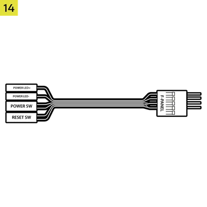
- Collegare la spina FPANEL al connettore I/O del pannello frontale della scheda madre, allineandola con la disposizione delle chiavi. Questo connettore è spesso contrassegnato con la sigla JFP1 su alcune schede madri.
SUGGERIMENTO: se il PC non si accende o presenta problemi durante l'utilizzo della presa FPANEL, provare a utilizzare il cavo adattatore I/O frontale (14) in dotazione per garantire il corretto collegamento al connettore della scheda madre.
NOTA: questo case non include un LED HDD né un interruttore di reset, quindi, sebbene questi connettori siano presenti sul cavo adattatore I/O frontale (14), non sono funzionanti e sono stati intenzionalmente lasciati liberi.
2. SCHEDE MADRE AMD O INTEL NON STANDARD
- Utilizzare l'adattatore I/O frontale montato sulla parte superiore (14) incluso per collegare la spina FPANEL ai singoli pin del connettore I/O del pannello frontale.
3. FRONT PANEL 5V ARGB CONNECTION (FRAME 4000X only)
- Run the +5V ARGB cable through the passthrough filter and into your case.
- Plug the +5V ARGB cable into your motherboard for easy ARGB control or use a COMMANDER DUO for full iCUE synchronization.
NOTE: For standard FRAME 4000D configurations without the passthrough hole in the front panel I/O, you must use the front fan filter included with the front panel and route the ARGB cable through the bottom right edge to pass it into the chassis. This wire is able to be split in half for easier routing during installation.
4. FRONT I/O EXPLANATION
- TELAIO 4000D
- TELAIO 4000D RS
- TELAIO 4000D RS ARGB
- FRAME 4000X
| a.Pulsante di accensione + LED | c.2x USB 3.2 Gen 1 Tipo-A (5 Gbps) |
| b.Jack combinato per cuffie/microfono | d.1x USB 3.2 Gen 2x2 Type-C (20 Gbps) |
- TELAIO 4000D LCD RS ARGB
- SERIE FRAME 4000D VAULT
| a.Pulsante di accensione + LED | c. 2x USB 3.2 Gen 1 Type-C (5 Gbps) |
| b.Jack combinato per cuffie/microfono | d.1x USB 3.2 Gen 2x2 Type-C (20 Gbps) |
5. FRONT I/O CONNECTIONS
| a. HD Audio (Headphone, Microphone) | d. USB 3.2 Type-E (20 Gbps) |
| b. FPANEL (Power LED, Power Button) | e. +5V ARGB (FRAME 4000X only)* |
| c. USB 3.0 |
6. SWAPPING FRONT PANEL BUTTON POWER KEY SWITCH
The power button of the ELITE Front Panel I/O used in the FRAME 4000D LCD case utilizes a standard MX-Style key switch. This key switch is removable and replaceable to customize the look and feel of your power button.
- Simply pop off the plastic bezel on the front panel I/O and extract the key switch. Replace with a switch of your choice.
INSTALLAZIONE DELLA BANDA MAGNETICA
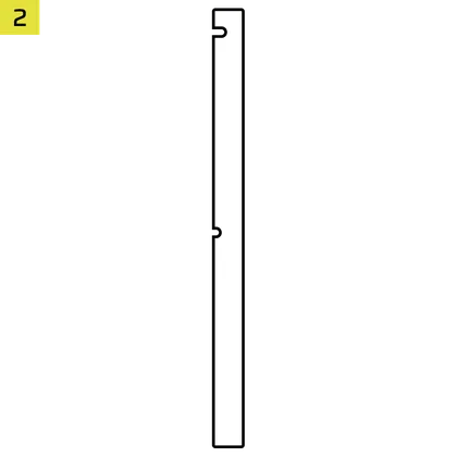
Il FRAME 4000 include una striscia magnetica per connettori inversi (2) progettata per coprire il bordo visibile dei fori dei connettori inversi nel vassoio della scheda madre.
- Allinea la striscia magnetica del connettore inverso (2) ai distanziatori e regola lateralmente per chiudere lo spazio sulla scheda madre.
1. SCHEDA MADRE CON CONNETTORI INVERTI
Se si installa una scheda madre con connettori inversi, è possibile utilizzare la striscia magnetica per connettori inversi (2) per riempire lo spazio intorno alla porta ATX a 24 pin, ottenendo un aspetto più pulito e rifinito.
2. SCHEDE MADRE CON CONNETTORI STANDARD
Quando si installa una scheda madre standard, è possibile far scorrere la striscia magnetica del connettore inverso (2) dietro la scheda, allineandola con i fori delle viti lungo il vassoio della scheda madre, per coprire lo slot del connettore inverso e nascondere eventuali cavi che corrono lungo il vassoio della scheda madre, ottenendo così un aspetto più pulito.
TIP: The magnetic strip features cut-out slots, allowing you to install it simultaneously with a GPU anti-sag stabilization arm mini mount.
INSTALLAZIONE DEL VENTILATORE
| FRAME 4000D RS/RS ARGB | ||||||
|
Front |
Top |
Rear |
Side |
PSU Shroud | Bottom | |
|
3x 120mm 2x 140mm 2x 200mm |
3x 120mm 2x 140mm
|
1x 120mm 1x 140mm
|
3x 120mm 2x 140mm
|
2x 120mm |
None |
|
|
FRAME 4000D LCD, FRAME 4000D WOOD, FRAME 4000X |
||||||
|
Front |
Top |
Rear |
Side |
PSU Shroud | Bottom | |
|
3x 120mm 2x 140mm 2x 200mm |
3x 120mm 2x 140mm
|
1x 120mm 1x 140mm
|
3x 120mm 2x 140mm
|
2x 120mm |
1x 120mm |
|
USING THE INFINIRAIL™ FAN MOUNTING SYSTEM
CORSAIR's InfiniRail™ is an innovative fan and radiator mounting system designed to offer exceptional flexibility and ease of use in PC case builds. Unlike traditional cases with fixed mounting points, InfiniRail utilizes adjustable steel rails that allow users to slide and position fans and radiators precisely where needed.
Il FRAME 4000 è dotato di due sistemi InfiniRail: uno nella parte superiore e uno nella parte anteriore.
NOTE: Determine the size and placement of your fans before configuring the rails. You do not have to fully remove the InfiniRail Phillips head screws.
Regolazione delle guide nella parte anteriore del case
- Loosen the Phillips head screw on both ends of the InfiniRails.
- Regola entrambe le guide anteriori per le ventole in base ai segni presenti sul case.
NOTE: If using 200mm fans in front, you may need to remove the PSU shroud depending on your version of FRAME 4000 Series.
Regolazione della guida sulla parte superiore della custodia
- Loosen the Phillips head screw on both ends of the InfiniRail.
- Regola la guida superiore dei ventilatori in base ai segni presenti sul case.
IMPORTANTE: le viti con teste di forma non standard non devono essere rimosse.
2. INSTALLAZIONE DELLE VENTOLE NELLA PARTE ANTERIORE
Installazione di ventole da 120 mm o 140 mm
Per installare ventole da 120 mm o 140 mm utilizzando il sistema di montaggio delle ventole InfiniRail frontale, è necessario installare i supporti per ventole InfiniRail (3). Utilizzare quattro supporti per ogni ventola, due su ciascun lato delle guide.
NOTA: alcuni modelli potrebbero essere dotati di supporti per ventole InfiniRail preinstallati.
- Fissare i supporti per ventola InfiniRail (3) alle guide ancorando prima il bordo interno di ciascun supporto, quindi facendo scattare il bordo esterno in posizione.
- Fai scorrere i supporti lungo le guide per allinearli ai punti di montaggio della ventola.
- Allineare le ventole alle linguette di montaggio sui supporti e fissarle avvitando le viti autofilettanti per ventole (7).
- Una volta allineato, è possibile bloccare il dispositivo in posizione con le viti di bloccaggio del supporto della ventola InfiniRail (13).
Installazione di ventole da 200 mm
Le ventole da 200 mm si avvitano direttamente ai supporti InfiniRail senza i supporti in plastica. Rimuovere i supporti se sono preinstallati sul case.
- Allineare le ventole alle fessure di montaggio sulle InfiniRails e fissarle avvitando le viti autofilettanti per ventole (7) nel telaio della ventola.
NOTA: per l'installazione di alcune ventole da 200 mm potrebbe essere necessario rimuovere la copertura dell'alimentatore.
NOTE: When installing 200 mm front fans, the side fan bracket or cable cover must be mounted in the secondary position (towards the motherboard tray) to provide sufficient clearance.
3. INSTALLAZIONE DELLE VENTOLE SULLA PARTE SUPERIORE
- Allineare le ventole agli slot di montaggio InfiniRail e fissarle avvitando le viti autofilettanti (7) nel telaio della ventola.
4. INSTALLAZIONE DELLE VENTOLE SUL LATO
Per installare le ventole sul lato, assicurarsi di aver installato la staffa di montaggio della ventola laterale (1).
- Allineare le ventole alle fessure di montaggio e fissarle avvitando le viti autofilettanti (7) nel telaio della ventola.
SUGGERIMENTO: utilizzare i punti contrassegnati sulla staffa di montaggio della ventola laterale (1) come guide di centraggio.
5. INSTALLAZIONE DELLE VENTOLE SULLA COPERTURA DELL'ALIMENTATORE
- Align your fans to the fan mounting holes on the PSU Shroud.
- Fissare le ventole con viti lunghe per ventole (8).
6. INSTALLAZIONE DELLE VENTOLE NELLA PARTE POSTERIORE
- Allinea la ventola ai fori di montaggio della ventola.
- Fissare la ventola avvitando le viti autofilettanti per ventole (7).
7. INSTALLING FANS IN THE BOTTOM
- Align your fans to the fan mounting holes.
- Secure the fans with Long Fan Screws (8).
NOTE: Not all FRAME 4000 Series variants can install a bottom fan. Refer to the fan location table for your particular case.
SUPPORTO DI RAFFREDDAMENTO PERSONALIZZATO HYDRO X
The FRAME 4000 has fill / drain ports pre-punched in the top and bottom panels for a Hydro X open loop liquid cooling setup.
- Rimuovere i coperchi delle porte facendo leva delicatamente con un cacciavite a testa piatta.
INSTALLAZIONE DEL RADIATORE
Il FRAME 4000 offre diverse posizioni per il montaggio di un radiatore per il raffreddamento a liquido, con le posizioni frontale e superiore dotate di un supporto per ventola InfiniRail regolabile. Per ulteriori dettagli sull'utilizzo del sistema di montaggio della ventola InfiniRail, consultare la sezione Installazione della ventola.
SUGGERIMENTO: per ottenere prestazioni ottimali in termini di rumorosità, dissipazione termica e affidabilità, assicurarsi che il radiatore sia montato più in alto rispetto alla pompa quando si utilizza un sistema AIO.
|
Fronte |
Inizio pagina |
Posteriore |
Lato |
Copertura PSU |
|
240 mm 280 mm 360 mm |
240 mm 280 mm 360 mm |
120 mm 140 mm |
240 mm 280 mm 360 mm |
Nessuno |
Il montaggio superiore garantisce prestazioni ottimali in termini di rumorosità, ma è possibile utilizzare anche altri tipi di montaggio in base alle proprie preferenze di assemblaggio. Consultare il manuale del prodotto del proprio dispositivo di raffreddamento per ulteriori suggerimenti sull'uso e sulle migliori pratiche.
1. OPTIMAL RADIATOR MOUNTING CONFIGURATION
NOTA: per centrare il radiatore, potrebbe essere necessario rimuovere una vite di montaggio del radiatore. L'utilizzo di undici viti fornisce comunque punti di montaggio sufficienti per installare in modo sicuro il radiatore e le ventole.
INSTALLAZIONE DI DISPOSITIVI DI MEMORIA E CONTROLLER
FRAME 4000 Series cases include up to two Combination Drive Plates - with each capable of mounting one HDD or two SSDs.
1. RIMOZIONE DELLA PIASTRA DI TRASMISSIONE COMBINATA
- Svitare la vite a testa zigrinata che fissa la piastra di azionamento combinata (E), quindi rimuovere la piastra.
2. INSTALLAZIONE DELL'SSD SULLA PIASTRA DI COMBINAZIONE DEL DRIVE
- Installare gli SSD sulla piastra combinata (E) fissandoli alla parte inferiore della piastra utilizzando le viti SSD incluse (10).
3. INSTALLAZIONE DELL'HDD SULLA PIASTRA DI COMBINAZIONE DELLE UNITÀ
- Installare l'HDD sulla piastra combinata dell'unità (E) fissandolo alla parte inferiore della piastra utilizzando le viti HDD incluse (9).
La piastra di azionamento combinata (E) funge anche da punto di montaggio per un controller hub del sistema iCUE LINK, se utilizzato.
4. FISSAGGIO DELLA PIASTRA DI TRASMISSIONE COMBINATA
Reinserire la piastra di azionamento combinata (E) nell'apposito alloggiamento nel case, quindi fissarla serrando la vite a testa zigrinata in senso orario.
INSTALLAZIONE DELL'ALIMENTATORE
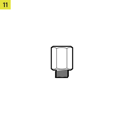
1. INSTALLAZIONE STANDARD DELL'ALIMENTATORE
- Installare l'alimentatore con la ventola rivolta verso il basso.
- Fissare l'alimentatore al telaio con le due viti imperdibili situate sul retro del case.
- Per maggiore sicurezza, fissare l'alimentatore utilizzando due viti della scheda madre (9) negli angoli del pannello posteriore.
2. INSTALLAZIONE DELL'ALIMENTATORE CORSAIR SHIFT
Il FRAME 4000 è completamente compatibile con tutti gli alimentatori SHIFT e si installa in modo identico a un alimentatore ATX standard.
INSTALLAZIONE DELLA SCHEDA GRAFICA
La staffa PCI inclusa consente al FRAME 4000 di supportare configurazioni di montaggio della GPU sia orizzontali che verticali.
SUGGERIMENTO: per facilitare il montaggio, installare la GPU come ultimo passaggio.
1. INSTALLAZIONE DI UNA GPU IN ORIENTAMENTO STANDARD
- Svitare i coperchi degli slot PCIe e rimuoverli.
- Inserire la scheda nello slot PCIe fino a quando non scatta in posizione con il meccanismo di ritenzione dello slot PCIe.
- Allinea la staffa con gli slot PCIe e fissa la scheda al case.
2. UTILIZZO DEL BRACCIO DI STABILIZZAZIONE ANTI-CULLA DELLA GPU
Il braccio di stabilizzazione anti-cedimento della GPU sostiene la scheda grafica, impedendole di piegarsi o cedere sotto il peso del dissipatore di calore. Questo non solo aiuta a proteggere la scheda grafica e lo slot PCIe, ma contribuisce anche a rendere il sistema più pulito e dall'aspetto più professionale.
- Regolare il braccio anti-cedimento della GPU allentando la vite a testa zigrinata frontale e facendolo scorrere verso l'alto o verso il basso.
NOTA: se la ventola della GPU o altre parti entrano in contatto con il braccio in gomma, utilizzare il distanziale in gomma per braccio di stabilizzazione anti-cedimento (6) incluso nella confezione degli accessori per garantire lo spazio necessario rispetto alle parti in movimento.
- Fissare il distanziale in gomma autoadesivo per braccio di stabilizzazione anti-abbassamento (6) al braccio anti-abbassamento della GPU.
SUGGERIMENTO: se decidi di sostituire la copertura del cavo (F) con la staffa di montaggio laterale della ventola (1), puoi riposizionare il braccio di stabilizzazione anti-cedimento della GPU sul mini supporto del braccio di stabilizzazione anti-cedimento (5) e mantenere la funzionalità anti-cedimento.
3. INSTALLAZIONE DI UNA GPU IN ORIENTAMENTO VERTICALE
Il FRAME 4000 supporta il montaggio verticale della GPU con la piastra PCI inclusa (B) e una scheda riser PCIe (venduta separatamente).
- Smontare la piastra PCI (B) rimuovendo le tre viti sul retro del case.
NOTA: Le viti a testa zigrinata della piastra PCI sono imperdibili e non è necessario rimuoverle completamente.
- Ruotare la piastra PCI (B) di 90 gradi in senso antiorario in modo che le viti a testa zigrinata del coperchio dello slot PCIe siano rivolte verso l'alto.
- Ricollegare la piastra PCI (B) e fissare le viti a testa zigrinata.
- Install the Vertical Mount Standoffs (12) from the accessory box to the top of the PSU shroud. There are two locations for standoffs, so choose the location that best suits the size of your GPU in relation to how far it is from the side panel.
- Mount the PCIe Riser Card (sold separately) to the Vertical Mount Standoffs (12) using two of the included Motherboard Screws (9).
- Montare la GPU nella staffa PCI inserendola saldamente nella scheda riser fino a quando non scatta in posizione, quindi fissarla con le viti a testa zigrinata.
CONNETTERE I TUOI FAN
1. CONNECTING AND CONTROLLING RS FANS
- FRAME 4000D RS
- FRAME 4000D WOOD RS
- FRAME 4000X
Per istruzioni sull'installazione della ventola, consultare la Guida rapida della serie CORSAIR RS.
2. CONNECTING AND CONTROLLING RS ARGB FANS
- FRAME 4000D RS ARGB
- FRAME 4000D LCD RS ARGB
Per istruzioni sull'installazione delle ventole, consultare la Guida rapida della serie CORSAIR RS ARGB.
MANUTENZIONE
1. PULIZIA DEI FILTRI DELLA CUSTODIA
Il modello FRAME 4000 è dotato di tre filtri antipolvere rimovibili. Un filtro di alimentazione nella parte inferiore, un filtro magnetico sul lato e un filtro in plastica/nylon nella parte anteriore.
- Per rimuovere il filtro della ventola anteriore (J), inclinare il telaio del filtro in plastica verso la parte superiore del case, tirando dalla parte inferiore.
- Per rimuovere il filtro magnetico della ventola laterale (H), tirare al centro per flettere il telaio, quindi staccare le estremità dai punti di bloccaggio e sollevare il filtro.
- Per rimuovere il filtro della ventola dell'alimentatore (K), tirarlo via dal case.
NOTA: i filtri possono essere puliti con aria compressa o acqua. Se si risciacquano i filtri, assicurarsi che siano completamente asciutti prima di reinstallarli.
2. CONSIGLI PER LA GESTIONE DEI CAVI
Il FRAME 4000 include altre varie funzioni di gestione dei cavi, quali:
- Cinghie interne/esterne regolabili con chiusura a strappo per il retro della custodia.
- Posizioni multiple per cinghie a strappo per adattarsi a schede madri con connettori standard o inversi.
- I punti di fissaggio con fascette sono posizionati strategicamente per instradare i cavi di alimentazione verso dispositivi specifici.
- Il cavo iCUE LINK si aggancia al pannello superiore per fissare saldamente i cavi LINK senza fissarli in modo permanente.
- Supports most reverse connector motherboards (MSI, ASUS, GIGABYTE) that feature connectors on the rear of the board for a build with no visible motherboard cables.
- Una posizione dedicata per il tuo hub di sistema iCUE LINK.
- Se non avete voglia di dedicare molto tempo alla gestione dei cavi e non volete che questi siano visibili attraverso il pannello inferiore in rete metallica, sostituite l'inserto traslucido con l'inserto oscurante in tinta incluso nella confezione degli accessori.
CERTIFICAZIONE DI GARANZIA

I case CORSAIR per la serie FRAME 4000 hanno una garanzia di 2 anni.
PRODUCT CHANGES
|
January 2025 |
Initial Release |
|
March 2026 |
Thicker steel side panels 200mm fan compatibility PSU shroud cut Various case rigidity improvements |
AVAILABLE ACCESORIES
CC-8900917 FRAME 4000 3D-Y Airflow Front Panel - Black
CC-8900918 FRAME 4000 3D-Y Airflow Front Panel - White
CC-8901149 FRAME 4000 RGB FLOW Front Panel - Black
CC-8901150 FRAME 4000 RGB FLOW Front Panel - White
CC-8901151 FRAME 4000 Series WOOD Front Panel - Black/Walnut
CC-8901152 FRAME 4000 Series WOOD Front Panel - White/Oak
CC-8901153-WW FRAME 4000 Series ELITE WOOD Front Panel - Black/Walnut
CC-8901154-WW FRAME 4000 Series ELITE WOOD Front Panel - White/Oak
CC-8901155 FRAME 4000 Series Flat Glass Front Panel - Black
CC-8901156 FRAME 4000 Series Flat Glass Front Panel - White
CC-8901157 FRAME 4000 Series Pixel Glass Front Panel - Black
CC-8901158 FRAME 4000 Series Pixel Glass Front Panel - White
CC-8901208 FRAME 4000 Glass + Mesh Side Panels - Black
CC-8901209 FRAME 4000 Glass + Mesh Side Panels - White
CC-8901147 FRAME 4000 Full Tempered Glass Side Panel - Black
CC-8901148 FRAME 4000 Full Tempered Glass Side Panel - White
CC-8901048-WW FRAME 4000 Series LCD Mounting Kit - Black
CC-8901049-WW FRAME 4000 Series LCD Mounting Kit - White
CC-8901142-WW FRAME 4000 Series Cold Air Intake Kit - Black
CC-8901143-WW FRAME 4000 Series Cold Air Intake Kit - White
CC-8901171 FRAME 4000 Series - Flat Steel Panel - Black
CC-8901172 FRAME 4000 Series - Flat Steel Panel - White
CC-8900966 FRAME Standard Steel Motherboard Tray - Black
CC-8900967 FRAME Standard Steel Motherboard Tray - White
CC-8901022 FRAME RapidRoute 2.0 Motherboard Tray - Black
CC-8901023 FRAME RapidRoute 2.0 Motherboard Tray - White
CC-8901146-WW FRAME ELITE Motherboard Tray - Meteorite Aluminum
CC-8900937 FRAME 4000 Full Length PSU Shroud - Black
CC-8900938 FRAME 4000 Full Length PSU Shroud - White
CC-8901161 FRAME 4000/4500 Compact PSU Shroud - Black
CC-8901162 FRAME 4000/4500 Compact PSU Shroud - White
CC-8900919 FRAME 4000 Standard FPIO - Black (2xA; 1xC)
CC-8900920 FRAME 4000 Standard FPIO - White (2xA; 1xC)
CC-8901159-WW FRAME 4000 Series ELITE Front Panel I/O - Black (3xC + ARGB Cherry MX Style PWR Button)
CC-8901160-WW FRAME 4000 Series ELITE Front Panel I/O - White (3xC + ARGB Cherry MX Style PWR Button)
SPARE PARTS LISTING
|
CC-8900917 |
FRAME 4000D 3D-Y Airflow Front Panel, Black |
|
CC-8900918 |
FRAME 4000D 3D-Y Airflow Front Panel, White |
|
CC-8900919 |
FRAME 4000D Replacement Front I/O, Black |
|
CC-8900920 |
FRAME 4000D Replacement Front I/O, White |
|
CC-8900921 |
FRAME 4000D Replacement Front Bezel Assembly, Black |
|
CC-8900922 |
FRAME 4000D Replacement Front Bezel Assembly, White |
|
CC-8900923 |
FRAME 4000D Replacement Top Panel, Black |
|
CC-8900924 |
FRAME 4000D Replacement Top Panel, White |
|
CC-8900925 |
FRAME 4000D Replacement Three-Quarter Side Glass, Black |
|
CC-8900926 |
FRAME 4000D Replacement Three-Quarter Side Glass, Black |
|
CC-8900927 |
FRAME 4000D Replacement Y-Mesh Quarter Panel, Black |
|
CC-8900928 |
FRAME 4000D Replacement Y-Mesh Quarter Panel, White |
|
CC-8900929 |
FRAME 4000D Accessory Box, Black |
|
CC-8900930 |
FRAME 4000D Accessory Box, White |
|
CC-8900931 |
FRAME 4000D Replacement PCI Bracket, Black |
|
CC-8900932 |
FRAME 4000D Replacement PCI Bracket, White |
|
CC-8900933 |
FRAME 4000D Replacement Top InfiniRail, Black |
|
CC-8900934 |
FRAME 4000D Replacement Top InfiniRail, White |
|
CC-8900935 |
FRAME 4000D Replacement Front InfiniRail (Single), Black |
|
CC-8900936 |
FRAME 4000D Replacement Front InfiniRail (Single), White |
|
CC-8900937 |
FRAME 4000D Replacement PSU Shroud, Black |
|
CC-8900938 |
FRAME 4000D Replacement PSU Shroud, White |
|
CC-8900939 |
FRAME 4000D Replacement Drive/Controller Plate, Black |
|
CC-8900940 |
FRAME 4000D Replacement Drive/Controller Plate, White |
|
CC-8900941 |
FRAME 4000D Replacement Cable Cover, Black |
|
CC-8900942 |
FRAME 4000D Replacement Cable Cover, White |
|
CC-8900943 |
FRAME 4000D Replacement InfiniRail Fan Mounts (12pcs), Black |
|
CC-8900944 |
FRAME 4000D Replacement InfiniRail Fan Mounts (12pcs), White |
|
CC-8900945 |
FRAME 4000D Replacement Strap Kit, Black |
|
CC-8900946 |
FRAME 4000D Replacement Strap Kit, White |
|
CC-8900947 |
FRAME 4000D Replacement PSU Filter, Black |
|
CC-8900948 |
FRAME 4000D Replacement PSU Filter, White |
|
CC-8900949 |
FRAME 4000D Replacement Front Filter, Black |
|
CC-8900950 |
FRAME 4000D Replacement Front Filter, White |
|
CC-8900951 |
FRAME 4000D Replacement Side Filter, Black |
|
CC-8900952 |
FRAME 4000D Replacement Side Filter, White |
|
CC-8900953 |
FRAME Series GPU Anti-Sag Assembly, Black |
|
CC-8900954 |
FRAME Series GPU Anti-Sag Assembly, White |
LEGAL
©2026 CORSAIR MEMORY, Inc. All rights reserved. CORSAIR and the sails logo are registered trademarks of CORSAIR in the United States and/or other countries. All other trademarks are the property of their respective owners. Product may vary slightly from those pictured.
CONTENUTI CORRELATI


