MANUAL | QUICK START GUIDE
iCUE LINK TITAN II 360 RX LCD
HIGH-PERFORMANCE LCD LIQUID CPU COOLER
In this Guide


BEFORE YOU START
IMPORTANT: If you are using an AMD platform and want to mount the LCD horizontally, check which AMD mounting bracket you have below.
Bracket 1: Supports horizontal LCD mounting.
Bracket 2: Contact CORSAIR Technical Support for an updated AMD mounting bracket.
NOTE:
- Most newer PC cases include a CPU cut-out to allow access to the back of the motherboard. If your case does not include a cut-out, you will need to remove the motherboard from the case prior to installation.
- The iCUE LINK TITAN II 360 RX LCD comes with an integrated DisplayPort cable that needs to be connected to a DisplayPort output on your GPU. If your GPU doesn't have a DisplayPort output, you can use a DisplayPort output on your motherboard (if available), or an active adapter to convert a compatible video output to DisplayPort.
- Update iCUE to version 5.37 or higher, and the iCUE LINK System Hub to version 3.11.646 or higher. Both are required for proper functioning and control of the iCUE LINK TITAN II 360 RX LCD.
GETTING TO KNOW
1. iCUE LINK TITAN II 360 RX LCD
| 1. iCUE LINK TITAN II 360 RX LCD | 6. Fan and Radiator Mounting Screws |
| 2. iCUE LINK RX360 II Unified Frame RGB Fans | 7. Double-sided Adhesive Tape |
| 3. Intel and AMD Mounting Brackets | 8. iCUE LINK Cables |
| 4. PCIe Cover Slot | 9. USB Type-C Port (for ICUE LINK 2.1’’ LCD screen CapSwap) |
| 5. iCUE LINK System Hub | 10. iCUE LINK Port |
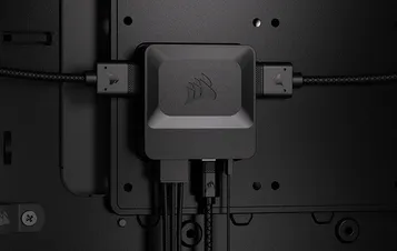
2. iCUE LINK SYSTEM HUB
| 11. iCUE LINK Ports | 13. USB Input |
| 12. Power Input | 14. Tach Output |
INCLUDED HARDWARE
1x Intel LGA 1851 / 1700
Mounting Bracket Set
1x Intel LGA 1851 / 1700
Backplate
1x AMD AM5 / AM4
Mounting Bracket Set
(Pre-installed)
12x Long Fan Screws
12x Radiator Screws
1x iCUE LINK RX360 II RGB
1x iCUE LINK System Hub
2x Double-sided Adhesive Tape
1x 500mm USB Type-C to USB 2.0 Cable
1x 800mm Tach Cable
1x 250mm iCUE LINK Cable With Dual 90° Connectors
1x 600mm iCUE LINK Cable With Dual 90° Connectors
1x 600mm iCUE LINK Cable With Straight / 90° Connectors
1x iCUE LINK 5′′ LCD Screen Module
1x PCIe Slot Cover
PREPARE iCUE LINK TITAN II 360 RX LCD FOR INSTALLATION
1. CONNECT iCUE LINK CABLES
- Connect one end of the 600mm iCUE LINK Cable (L) into the iCUE LINK TITAN II 360 RX LCD (1) fan housing as shown below.
TIP: To daisy-chain an optional rear-mounted iCUE LINK fan (sold separately), connect the 250mm cable (K) into the opposite side of the fan housing. Doing this before mounting the radiator ensures easy port access.
AMD INSTALLATION
IMPORTANT: A small number of initial units were shipped with AMD CPU mounting bracket that only allows for vertical orientation. If you have one of these units and want to use the horizontal orientation mounting on your AMD platform, please contact our technical support team for an updated AMD CPU mounting bracket.
1. PREPARE THE MOTHERBOARD FOR INSTALLATION
- Remove the existing AMD AM5/AM4 mounting brackets shown.
2. INSTALL THE PUMP UNIT
- Align the screws and pump over the backplate, then fasten the screws a few turns at a time in a cross pattern, alternating between opposite corners, until all four are tightened.
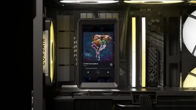
- Align the guide pin on the iCUE LINK 5" LCD Screen Module (N) with its corresponding slot on the pump base, then gently push the module onto the pump base to latch it in place.
3. CONNECT THE DISPLAY PORT CABLE
- Remove the top PCIe slot cover from the PCIe plate.
- Guide the DisplayPort cable from the iCUE LINK 5" LCD Screen Module (N) through the top-left cutout in the motherboard tray so it passes behind the motherboard, out of view.
- Route the cable downward behind the motherboard tray and out through the opening near the 24-pin motherboard connector.
- Guide the cable along the graphics card and out through the top opening in the PCIe plate.
- Seat the DisplayPort cable into the U-shaped cutout of the PCIe Slot Cover (O), then attach the cover to the PCIe plate.
- Connect the DisplayPort cable to the graphics card.
4. INSTALL THE RADIATOR
- If you are installing an additional rear iCUE LINK fan, daisy-chain it to your existing setup using the other end of the 250mm iCUE LINK Cable with Dual 90° Connectors (K).
- Mount the iCUE LINK TITAN II 360 RX LCD (1) inside the case with the Radiator Screws (E) as shown.
- Route the 600mm iCUE LINK Cable With Dual 90° Connectors (L) behind the motherboard.
INTEL INSTALLATION
1. PREPARE THE PUMP UNIT
- Remove the pre-installed AMD AM5 / AM4 Mounting Bracket Set (C).
- Attach the Intel LGA 1851 / 1700 Mounting Bracket (A).
2. INSTALL THE BACKPLATE
- Align the backplate (B) then adhere it with the self-adhesive side behind the motherboard.
3. INSTALL THE PUMP UNIT
- Align the screws and pump over the backplate, then fasten the screws a few turns at a time in a cross pattern, alternating between opposite corners, until all four are tightened.
- Align the guide pin on the iCUE LINK 5" LCD Screen Module (N) with its corresponding slot on the pump base, then gently push the module onto the pump base to latch it in place.
TIP: On Intel systems, the pump and LCD Screen Module assembly can be rotated 90° and installed in a horizontal orientation.
4. CONNECT THE DISPLAY PORT CABLE
- Remove the top PCIe slot cover from the PCIe plate.
- Guide the DisplayPort cable from the iCUE LINK 5" LCD Screen Module (N) through the top-left cutout in the motherboard tray so it passes behind the motherboard, out of view.
- Route the cable downward behind the motherboard tray and out through the opening near the 24-pin motherboard connector.
- Guide the cable along the graphics card and out through the top opening in the PCIe plate.
- Seat the DisplayPort cable into the U-shaped cutout of the PCIe Slot Cover (O), then attach the cover to the PCIe plate.
- Connect the DisplayPort cable to the graphics card.
5. INSTALL THE RADIATOR
- If you are installing an additional rear iCUE LINK fan, daisy-chain it to your existing setup using the other end of the 250mm iCUE LINK Cable with Dual 90° Connectors (K).
- Mount the iCUE LINK TITAN II 360 RX LCD (1) inside the case with the Radiator Screws (E) as shown.
- Route the 600mm iCUE LINK Cable With Dual 90° Connectors (L) behind the motherboard.
CONNECT THE TITAN II 360 RX LCD PUMP
- Insert the 90° connector from the 600mm iCUE LINK Cable (M) into the pump.
iCUE LINK SYSTEM HUB INSTALLATION
NOTE: The following steps show one of the many possible iCUE LINK connection configurations. The best setup for your build may vary depending on available space and the quantity, size, and orientation of your iCUE LINK components.
To learn more, visit our CORSAIR EXPLORER webpage.
* Product not included
1. CONNECT THE iCUE LINK CABLES
- Connect the iCUE LINK cables (L, M) to the iCUE LINK Ports (11) of the iCUE LINK System Hub (G).
2. CONNECT THE POWER CABLE
- Connect a 6-pin PCIe power cable from the power supply unit (PSU) to the Power Input (12) of the iCUE LINK System Hub (G).
3. CONNECT THE DATA CABLE
- Connect the USB Type-C to USB 2.0 Cable (I) into the USB Input (13) of the iCUE LINK System Hub (G).
- Connect the other end of the USB Type-C to USB 2.0 Cable (I) into a USB 2.0 header on the motherboard.
4. CONNECT THE TACH CABLE
- Connect the 2-pin end of the Tach Cable (J) into the Tach Output (14) on the iCUE LINK System Hub (G).
- Connect the other end of the Tach Cable (J) to the CPU_FAN header on the motherboard.
5. MOUNT THE SYSTEM HUB
- Mount the System Hub (G) inside the case magnetically or with the supplied tape.
SOFTWARE SETUP
1. INSTALL iCUE

2. UPDATE iCUE SOFTWARE
- Once iCUE is installed, run the software. The iCUE LINK TITAN II RX360 II, iCUE LINK 5" LCD Screen Module and iCUE LINK RX360 II RGB Fan tiles will appear in the iCUE interface.
- If any of the connected devices need a firmware update, you will be prompted to perform an update via a notification in the top right corner. You can also click the settings (cog wheel icon in the top right corner) and check for the software and firmware updates manually.
NOTE: Update iCUE to version 5.37 or higher, and the iCUE LINK System Hub to version 3.11.646 or higher. Both are required for proper functioning and control of the iCUE LINK TITAN II 360 RX LCD.
3. NEW DEVICE DETECTION
While the iCUE LINK System Hub and iCUE LINK TITAN II 360 RX LCD do not support hot-plugging, you can still quickly detect newly connected devices without powering down your PC by following these steps:
- Click on Settings cogwheel in the iCUE LINK System Hub tile.
- Click Start next to Device Enumeration to re-detect all connected devices.
4. LCD SCREEN BRIGHTNESS ADJUSTMENT
- Click on Settings cogwheel in the iCUE LINK 5" LCD Screen Module tile and use the brightness slider to adjust the desired brightness.
5. LIGHTING EFFECTS
Choose which lighting effect will be displayed when the iCUE software is running:
- Select either the iCUE LINK TITAN II RX360 II, iCUE LINK 5" LCD Screen Module or iCUE LINK RX360 II RGB Fan tile.
- Select "Lighting Effects" in the left-hand panel.
- If present, click an existing layer in the "Lighting Layers" panel to edit it, or click on the "+" button to create a new lighting layer.
- Select the desired lighting effect by clicking on one of the available options in the "Lighting Type" panel.
- In the "Quick Lighting Zones" panel, select the product you want to apply the selected effect to. Choose "All" to apply the selected effect to all listed products.
6. LIGHTING EFFECTS - DEVICE MEMORY MODE
Choose which lighting effect will be displayed when iCUE software is not running, usually during computer the startup phase:
- Toggle the Device Memory Mode by clicking the button.
- Select the desired lighting effect by clicking on one of the available options in the "Lighting Type" panel.
- Click on the memory card icon to save the setting.
7. LCD SCREEN SETUP
The Screen Setup page allows you to choose how the 5-inch LCD Screen Module is used and configure keyboard shortcuts for switching between screens.
- Select "Screen Setup" in the left-hand panel.
- In the bottom "Screen Setup" panel, select "iCUE Widgets" to display iCUE widgets, such as system monitoring, images/videos, or other customizable widgets.
- Select "Desktop" to use the LCD screen as a secondary desktop display.
- Assign a keystroke to "Switch Display Option" to toggle between "iCUE Widgets" and "Desktop" modes.
- Assign a keystroke to "Previous Display Screen" to switch to the previous screen page.
- Assign a keystroke to "Next Display Screen" to switch to the next screen page.
8. PAGES PERSONALIZATION
The Pages Personalization page allows you to customize the look of each LCD screen page.
- Select "Pages Personalization" in the left-hand panel.
- Select the page you want to personalize by clicking the page indicator under the screen preview image.
- Adjust the page theme, background, widget colors, and widget transparency using the options available in the bottom "Pages Personalization" panel.
- To add or change the background, click the "+" button next to "Device Background" and select a preset image or upload a custom one.
9. WIDGETS
The Widgets page allows you to add, configure and personalize iCUE Widgets.
- Select "Widgets" in the left-hand panel.
- Click the "+" button on the screen preview image to add a new widget.
- To add a new page, click the "+" button under the screen preview image.
- Select the desired widget from the bottom "Widgets" panel.
- Configure the selected widget using the various options in the bottom centre and right panels.
10. FANS SETUP
- Select iCUE LINK TITAN II RX360 II from the navigation bar.
- Select "Fans Setup" in the left-hand panel.
- Click the "Run Wizard" button in the info panel below.
If you have additional fans installed in your system, run the AIO Fans Setup Wizard to identify which fans are mounted on the radiator. This makes it easy to tell which fans are mounted on the radiator and which aren't when configuring different cooling presets.
- Select the fan(s) that are mounted on the radiator by clicking on the UI then click "finish".
11. COOLING SETUP
- Select either the iCUE LINK TITAN II RX360 II, iCUE LINK 5" LCD Screen Module or iCUE LINK RX360 II RGB Fan from the navigation bar.
- Select "Cooling" in the left-hand panel.
- Select the desired cooling preset for each device.
NOTE: For the AIO Cooler, use the iCUE LINK TITAN II RX360 II cooling profile for optimal fan control based on coolant temperature.
- Alternatively, click the “+” icon under “Cooling Presets” to create a new preset with a custom fan curve.
12. COOLING SETUP - DEVICE MEMORY MODE
Choose how your fan(s) will perform when iCUE software is not running, usually during computer the startup phase:
- Toggle the Device Memory Mode by clicking the button.
- Select the desired setting by clicking on one of the available options in the "Cooling Presets" panel.
- Alternatively click the “+” icon under “Cooling Presets” to create a custom fan curve.
- Click on the memory card icon to save the setting.
13. ALERT SETUP
The "Alerts" feature allows you to set custom alerts or trigger specific actions when your device reaches a certain temperature:
- Click “Alerts” to access the alerts page.
- Set the temperature values for triggering specific alert action.
FAQ
What is CapSwap technology and how does it work with the iCUE LINK TITAN II RX LCD CPU coolers?
With CapSwap, you can easily replace the pump cap with a functional module like the iCUE LINK VRM Fan (sold separately) to customize your iCUE LINK TITAN II RX RGB CPU cooler. Visit this link for a list of compatible CapSwap modules.
Do I need to connect a USB Type-C cable into the iCUE LINK TITAN II RX LCD pump?
No, it is not required for the iCUE LINK TITAN II LCD RGB to function properly. This USB Type-C port is used when upgrading to the iCUE LINK LCD module.
How do I know the direction of the airflow of the fan?
Arrows located on the side of the fan indicate the direction of the airflow.
My cooler and fans are blinking red or not functioning. What do I do?
If the fans on your system are blinking red, this is an indication that too many iCUE LINK devices are connected to a single port on the iCUE LINK System Hub. The maximum number of devices that can be connected to a single port is 12. To resolve this issue, please distribute the iCUE LINK devices across both available ports on the iCUE LINK System Hub. This will ensure adequate power distribution to all the connected devices.
If you continue to experience issues or find that the fans are not functioning at all, please perform the following:
- Double check all connections between the cooler and fans.
- Ensure that your devices are updated to the most recent firmware via iCUE Software.
If this does not resolve your problems, please open a support ticket or contact our customer support team for further troubleshooting and assistance at https://help.corsair.com/hc/requests/new.
In what orientation should I install my radiator?
Figure 1 shows the ideal radiator orientation. If case layout or clearance prevents this, use alternative setups like shown in Figure 2 and Figure 3. Whichever orientation you choose, always ensure the top of the radiator sits higher than the CPU pump.
Can I reuse the pre-applied thermal paste on the cooler for re-installation?
Re-installation of the iCUE LINK TITAN II RX LCD CPU cooler will require you clean off the pre-applied thermal paste and apply a new layer of thermal paste. We recommend using CORSAIR XTM70, sold separately.
What should I do if I lost or broke a specific part or accessory from the iCUE LINK TITAN II RX LCD CPU cooler?
Replacement parts for iCUE LINK TITAN II RX LCD CPU coolers are sold through the CORSAIR webstore.
Is the RX360 II RGB recognized as one device or three devices in iCUE?
The RX360 II RGB is detected as a single device in iCUE, with fan speed controlled and synchronized together.
Since the three fans operate as one unit, sharing the same RPM reporting, individual fan status is not separately displayed in iCUE. To help ensure proper operation, monitor for any unusual increases in CPU or system temperatures during normal workloads, as this may indicate reduced overall airflow or a potential issue within the fan group.
Why isn’t iCUE software detecting the LCD Screen module?
If the iCUE LINK 5” LCD Screen Module is not detected, first check whether your iCUE LINK TITAN II 360 RX LCD AIO cooler appears in iCUE. If the cooler is not detected, make sure the iCUE LINK cable connections are properly secured, then restart your system. If the cooler is detected, ensure the LCD module is properly installed
Can I use the iCUE LINK 5’’ LCD SCREEN MODULE as a monitor without iCUE?
Yes. When connected via DisplayPort (DP), the LCD Screen Module can function as a standard display without iCUE. However, iCUE enables additional features such as system monitoring widgets and display customization that are not available through Windows. For the best experience, we recommend using iCUE.
Do I need to keep the DisplayPort (DP) cable connected?
Yes, the DisplayPort (DP) connection must remain connected to use all LCD features. Without a DP connection, the screen will not display content. However, fan and RGB lighting control will continue to function normally through iCUE.
Does the iCUE LINK 5’’ LCD SCREEN MODULE support auto-rotation?
Yes, the LCD screen automatically adjusts its orientation based on how it is installed, ensuring the content is always displayed correctly.
POWER RATING
System Hub Output rating: 12Vdc 7A (per port)
RX360 II RGB Input rating: 12Vdc Max 1.39A / Typical 0.8A
WARRANTY

All CORSAIR iCUE LINK coolers have a 6-year warranty.
LEGAL
© 2026 CORSAIR MEMORY, Inc. All rights reserved. CORSAIR and the sails logo are registered trademarks of CORSAIR in the United States and/or other countries. All other trademarks are the property of their respective owners. Product may vary slightly from those pictured.
RELATED CONTENT