-
ESPECIFICACIONES DEL CHASIS
-
CONTENIDO DEL KIT DE ACCESORIOS
-
CASE EXPANDED VIEWS
-
INSTALACIÓN/DESINSTALACIÓN DE LOS PANELES
-
INSTALACIÓN DE LA PLACA BASE
-
INSTALACIÓN DE CABLES DE E/S FRONTALES
-
INSTALACIÓN DE LA BANDA MAGNÉTICA
-
INSTALACIÓN DEL VENTILADOR
-
SOPORTE DE REFRIGERACIÓN PERSONALIZADO HYDRO X
-
INSTALACIÓN DE RADIADORES
-
INSTALACIÓN DE DISPOSITIVOS DE ALMACENAMIENTO Y CONTROLADORES
-
INSTALACIÓN DE SUMINISTRO ELÉCTRICO
-
INSTALACIÓN DE LA TARJETA GRÁFICA
-
CONECTANDO A TUS FANS
-
MANTENIMIENTO
-
DECLARACIÓN DE GARANTÍA
-
PRODUCT CHANGES
-
AVAILABLE ACCESORIES
-
SPARE PARTS LISTING
-
LEGAL
- CONTENIDO RELACIONADO
MANUALES | GUÍA DE INICIO RÁPIDO
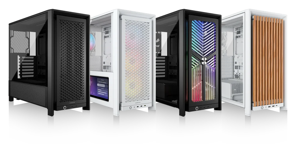
CORSAIR FRAME 4000 Series
MODULAR MID-TOWER CASE
La versión en inglés está disponible aquí. - English
Si tienes algún otro problema por favor contacta atención al cliente
ESPECIFICACIONES DEL CHASIS
|
Configuración de la ranura PCI |
7 horizontal y 3 vertical |
|
Compatibilidad con placas base |
Mini-ITX, Micro-ATX, ATX, E-ATX (305 mm x 277 mm) |
|
HDD |
|
|
SSD |
|
|
Colores disponibles |
|
|
Material del panel lateral izquierdo |
Vidrio templado |
|
Material del panel frontal |
|
|
Espacio para cables en la parte trasera |
37 mm |
|
Filtros de polvo |
Front, Side, Bottom |
|
Frontal de I/O |
Standard FPIO (FRAME 4000D, FRAME 4000D WOOD, FRAME 4000X):
ELITE FPIO (FRAME 4000D LCD, FRAME 4000D Vault SERIES):
|
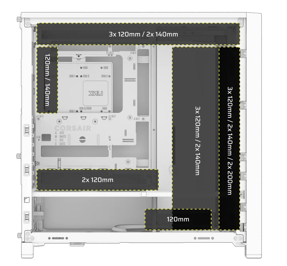
1. UBICACIONES DE LOS VENTILADORES
NOTE: No fans are included with the FRAME 4000D or FRAME 4000D Vault Series.
| FRAME 4000D RS/RS ARGB | ||||||
|
Parte delantera |
Arriba |
Parte trasera |
Lateral |
Cubierta de la fuente de alimentación | Bottom | |
|
3 x 120 mm 2 x 140 mm 2 x 200 mm |
3 x 120 mm 2 x 140 mm
|
1x 120 mm 1x 140 mm
|
3 x 120 mm 2 x 140 mm
|
2 x 120 mm |
None |
|
|
FRAME 4000D LCD, FRAME 4000D WOOD, FRAME 4000X |
||||||
|
Front |
Top |
Rear |
Side |
PSU Shroud | Bottom | |
|
3x 120mm 2x 140mm 2x 200mm |
3x 120mm 2x 140mm
|
1x 120mm 1x 140mm
|
3x 120mm 2x 140mm
|
2x 120mm |
1x 120mm |
|
2. VENTILADORES Y CONTROLADORES INCLUIDOS
|
MARCO 4000D |
MARCO 4000D RS | MARCO 4000D RS ARGB |
FRAME 4000D WOOD, FRAME 4000X |
FRAME 4000 LCD
|
|
|
Ninguno |
3x RS120 (Pre-installed) |
3x RS120 ARGB (Pre-installed) |
4x RS120 (Pre-installed) |
4x RS120 ARGB (Pre-installed) |
|
NOTE: Fans and lighting controllers are not included. ARGB lighting can be controlled through your motherboard or with a separate fan controller.
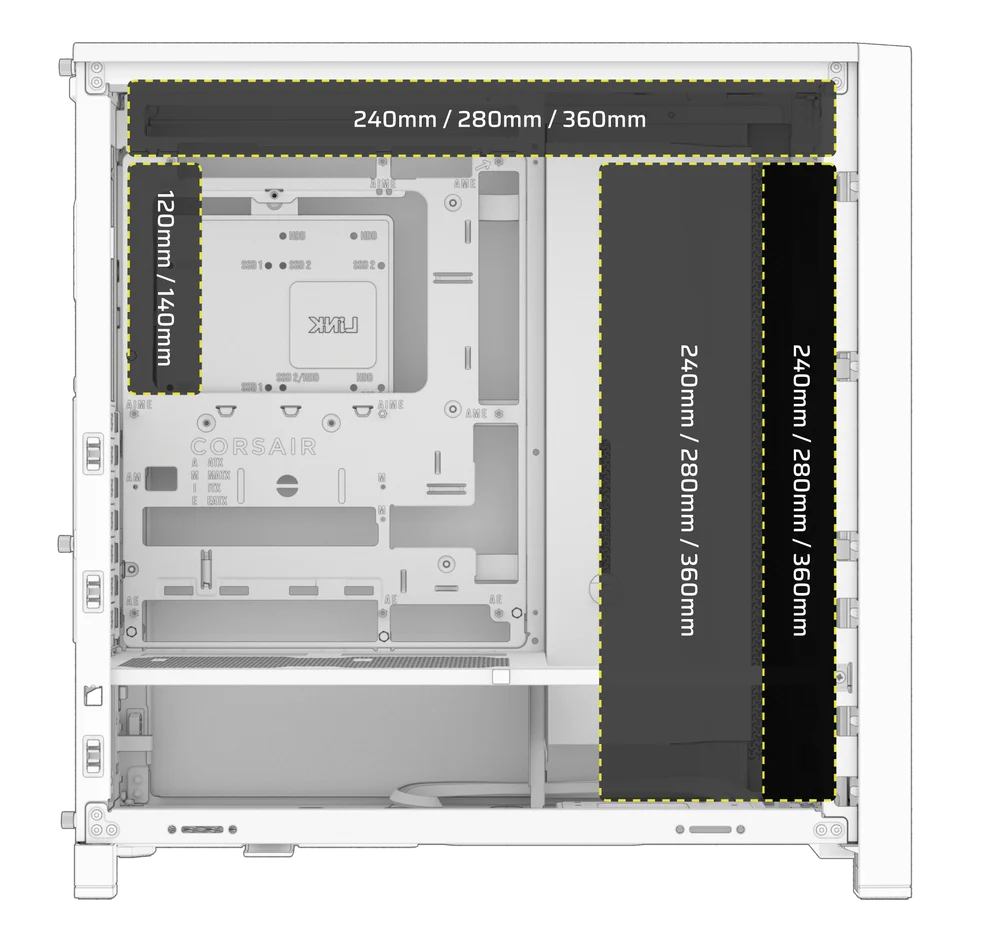
3. COMPATIBILIDAD DEL RADIADOR
|
Parte delantera |
Arriba |
Parte trasera |
Lateral |
Cubierta de la fuente de alimentación |
|
240 mm 280 mm 360 mm |
240 mm 280 mm 360 mm |
120 mm 140 mm |
240 mm 280 mm 360 mm |
Ninguno |
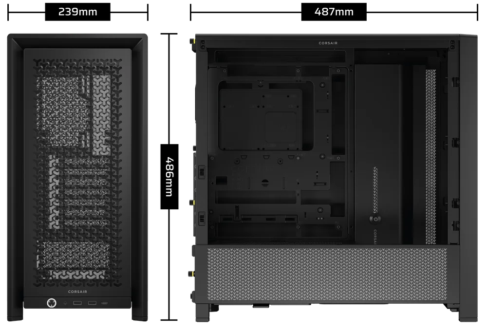
4. DIMENSIONES DE LA CAJA
| Dimensiones |
487 mm x 239 mm x 486 mm |
|
Longitud máxima de la GPU |
430 mm |
|
Altura máxima del refrigerador de la CPU |
170 mm |
|
Longitud máxima de la fuente de alimentación |
220 mm |
CONTENIDO DEL KIT DE ACCESORIOS
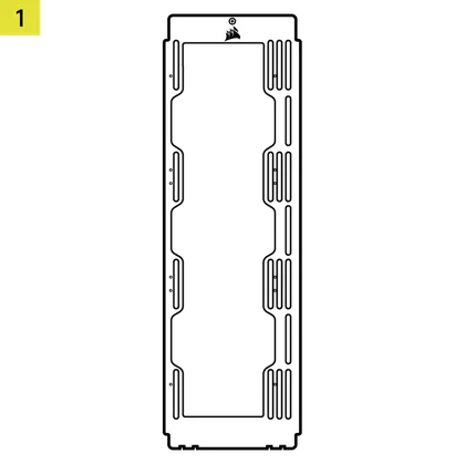
1x Soporte de montaje para ventilador lateral
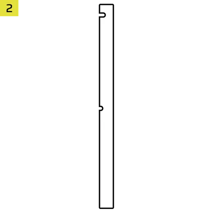
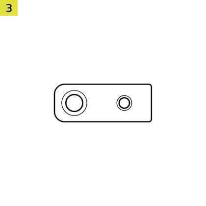
1x Conector inverso con banda magnética
12x InfiniRail Fan Mounts
(Pre-Installed on Select Cases)
1x Solid Side Insert
(Select Models)

1x GPU Anti-sag Stabilization Arm Mini Mount
1x GPU Anti-sag Stabilization Arm Rubber Spacer
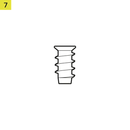
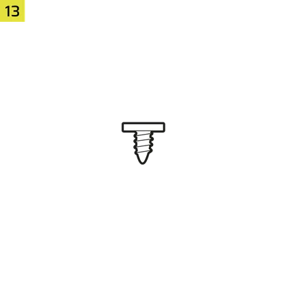
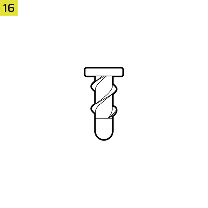
12-28x Self-Tapping Fan Screws
(Qty varies by model)
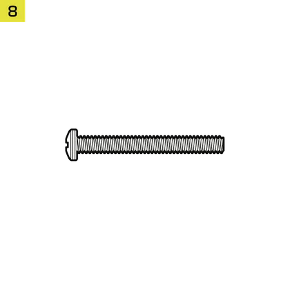
8-12x Long Fan Screws (6-32 UNC; 30mm)
(Qty varies by model)
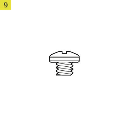
18 tornillos para placa base/disco duro (6-32 UNC; 6 mm)

8-16x SSD Screws (M3 x 0.5; 5mm)
(Qty varies by model)
1x Separador de placa base de repuesto

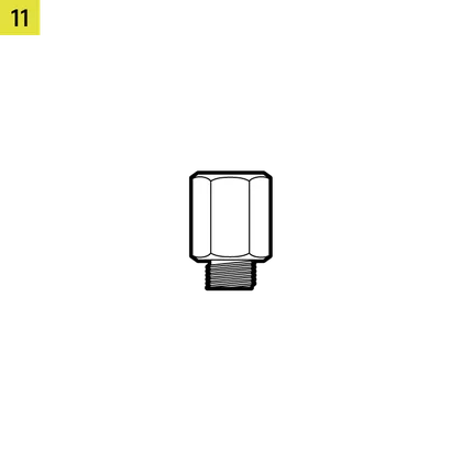
2 separadores de montaje vertical
InfiniRail Fan Mount Lock Screws
(Pre-Installed on Select Models)
1 cable adaptador de E/S frontal
3x or 4x RS120 / RS 120 ARGB Fans
(Pre-Installed on Select Models)
12x QuikTurn® Fan Screws
(Select Models)

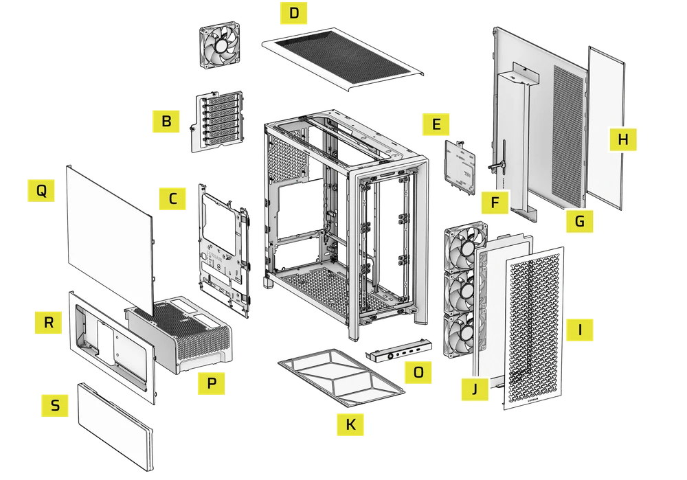
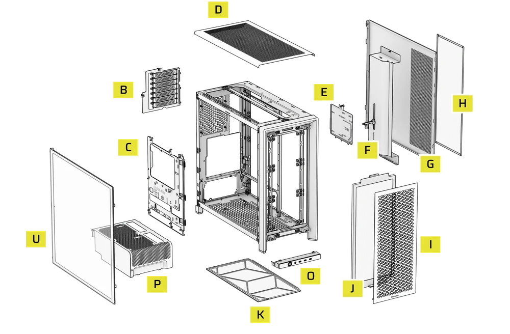
CASE EXPANDED VIEWS
FRAME 4000D RS/RS ARGB

| A. Panel lateral con tres cuartas partes de vidrio | H. Filtro del ventilador lateral |
| B. Placa PCI | I. Panel frontal |
| C. Bandeja de acero estándar para placa base | J. Filtro del ventilador frontal |
| D. Panel superior | K. Filtro del ventilador de la PSU |
| E. Placa de accionamiento/controlador | L. Cubierta de la PSU |
| F. Cable Shroud with GPU Anti-sag Stabilization Arm | M. Inserto lateral translúcido |
| G. Panel lateral de acero | N. Panel lateral con una cuarta parte de malla |
FRAME 4000D LCD
| B. PCI Plate | J. Front Fan Filter |
| C. Standard Steel Motherboard Tray | K. PSU Fan Filter |
| D. Top Panel | O. Front Panel I/O |
| E. Drive / Controller Plate | P. Compact PSU Shroud |
| F. Cable Shroud with GPU Anti-sag Stabilization Arm | Q. Two-Thirds Side Glass Panel |
| G. Steel Side Panel | R. LCD Screen Mounting Bracket |
| H. Side Fan Filter | S. XENEON EDGE LCD Touchscreen |
| I. Front Panel |
FRAME 4000X
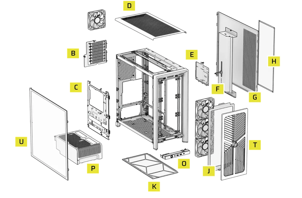
| B. PCI Plate | J. Front Fan Filter |
| C. Standard Steel Motherboard Tray | K. PSU Fan Filter |
| D. Top Panel | O. Front Panel I/O |
| E. Drive / Controller Plate | P. Compact PSU Shroud |
| F. Cable Shroud with GPU Anti-sag Stabilization Arm | T. RGB FLOW Front Panel |
| G. Steel Side Panel | U. Full Tempeed Side Glass Panel |
| H. Side Fan Filter |
FRAME 4000D WOOD

| B. PCI Plate | J. Front Fan Filter |
| C. Standard Steel Motherboard Tray | K. PSU Fan Filter |
| D. Top Panel | O. Front Panel I/O |
| E. Drive / Controller Plate | P. Compact PSU Shroud |
| F. Cable Shroud with GPU Anti-sag Stabilization Arm | U. Full Tempered Glass Side Panel |
| G. Steel Side Panel | V. Wood Front Panel |
| H. Side Fan Filter |
FRAME 4000D Vault Series
| B. PCI Plate | I. Front Panel |
| C. Standard Steel Motherboard Tray | J. Front Fan Filter |
| D. Top Panel | K. PSU Fan Filter |
| E. Drive / Controller Plate | O. Front Panel I/O |
| F. Cable Shroud with GPU Anti-sag Stabilization Arm | P. Compact PSU Shroud |
| G. Steel Side Panel | U. Full Tempered Side Glass Panel |
| H. Side Fan Filter |
INSTALACIÓN/DESINSTALACIÓN DE LOS PANELES
ADVERTENCIA: Este producto contiene vidrio templado. Manipular con cuidado.
- Para evitar daños o lesiones, evite colocar o guardar la funda sobre superficies duras, como baldosas de cerámica o porcelana, piedra, mampostería u hormigón.
- CORSAIR recomienda encarecidamente retirar todos los paneles laterales de cristal templado antes de colocar la carcasa o comenzar el montaje sobre una superficie dura.
- Si debe colocar la estructura terminada sobre una superficie dura, eleve o aísle la carcasa para minimizar el riesgo de contacto accidental, daños o lesiones personales.
Los paneles de repuesto están disponibles en www.corsair.com. Póngase en contacto con help.corsair.com si necesita ayuda.
1. DESMONTAJE DE LOS PANELES LATERALES
NOTE: This case is available with different left side panel designs (full glass or split glass/steel). Depending on your model, you may have one or multiple panels to remove. The removal method is the same for all variants.
- To remove the left side panel(s), loosen the thumbscrews at the rear of the case, then swing the panel(s) outward from the back and lift them off the front mounting tabs.
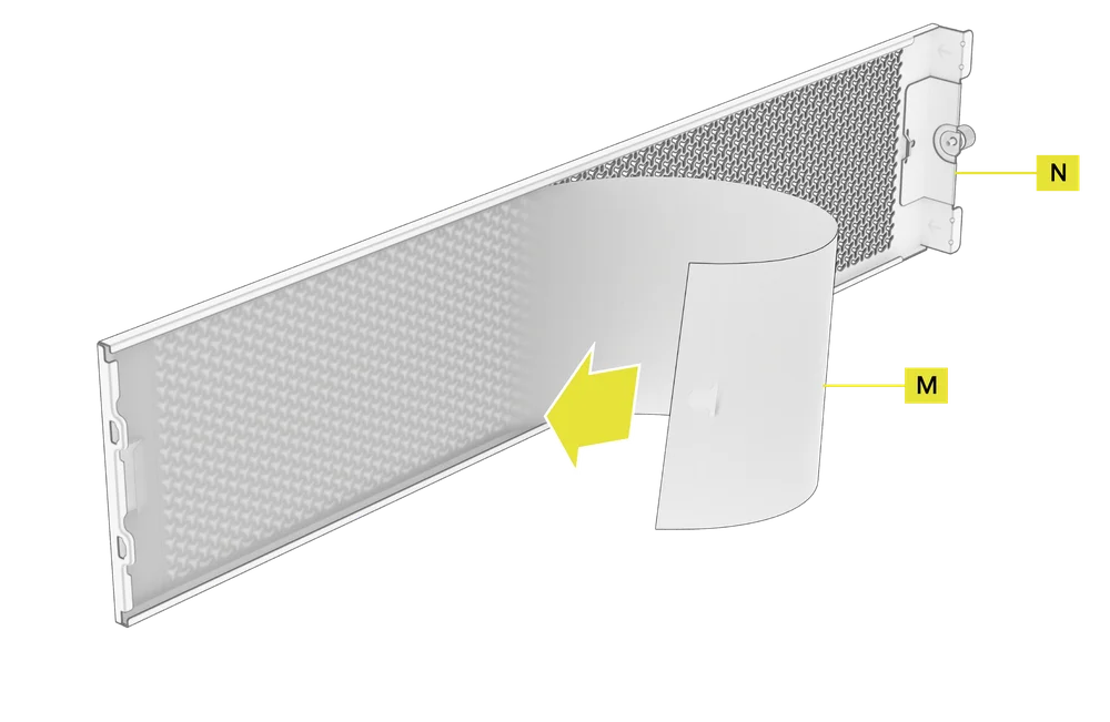
NOTE: On models equipped with the Quarter Mesh Side Panel (N), two optional inserts are included to customize the look and function of your build. A Translucent Side Insert (M) comes pre-installed, allowing RGB lighting to shine through while partially concealing cables. Alternatively, you can install the Solid Side Insert (4) for full coverage, or leave the panel open for maximum airflow. Inserts slide under the long edges of the panel for quick installation and removal.
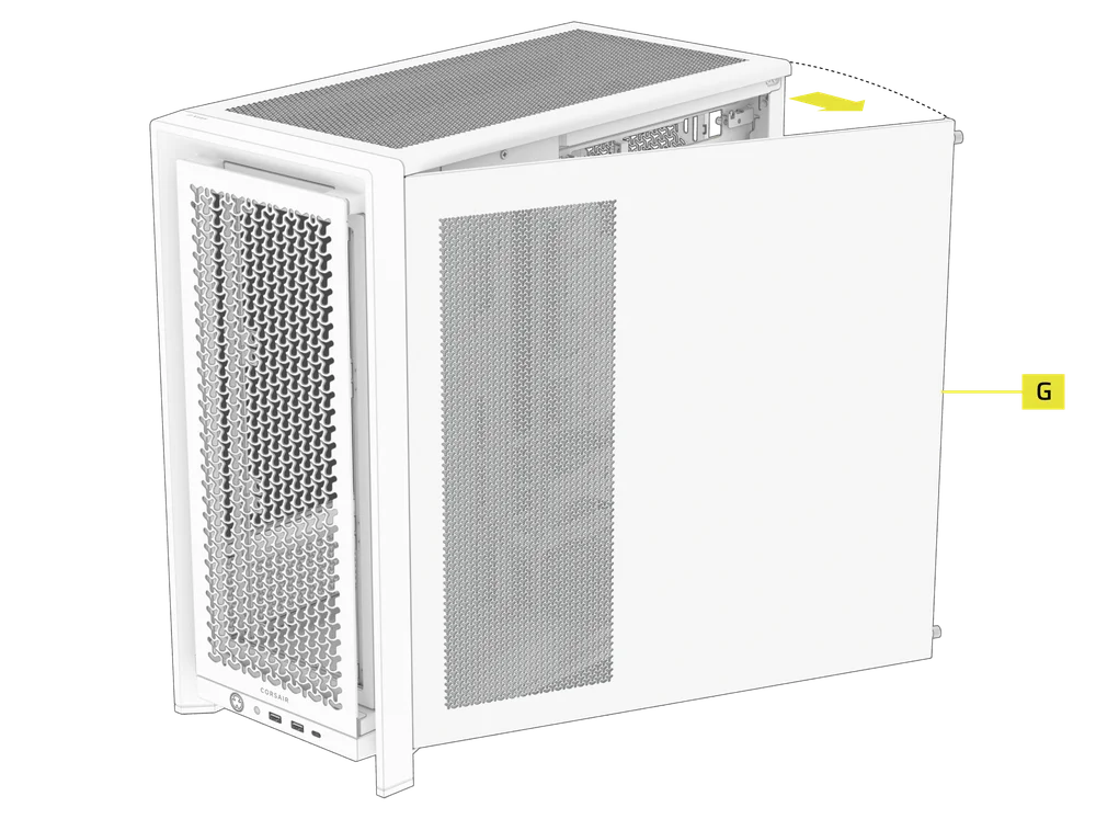
- Para retirar el panel lateral de acero (G), desatornille el panel de la parte posterior de la carcasa y gírelo hacia fuera desde las pestañas hacia la parte delantera de la carcasa.
TIP: For removal or use of accessory side panels, please reference these Quick Start Guides for more in-depth information:
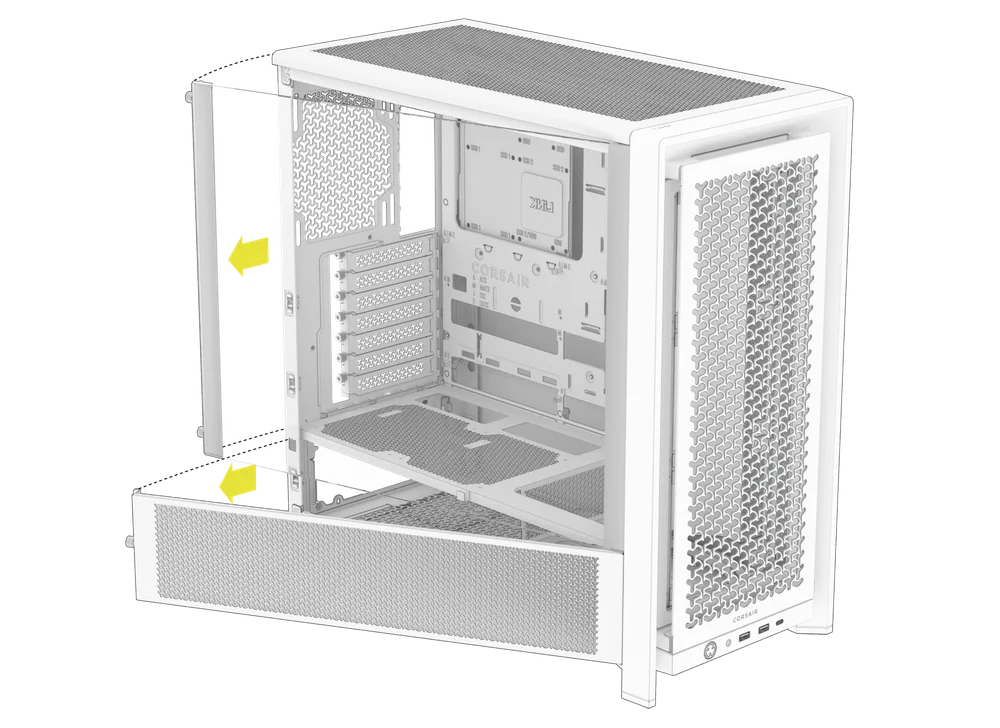
2. DESMONTAJE DEL PANEL FRONTAL
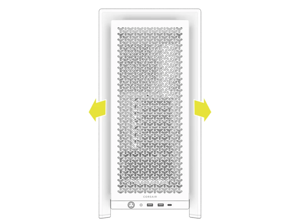
- Pull the Front Panel outward. It's secured by two ball snaps at the top and bottom.
3. RETIRADA DEL PANEL SUPERIOR
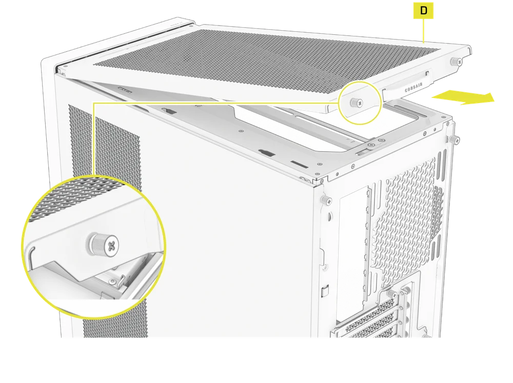
- Desatornille los dos tornillos de mariposa cautivos de la parte trasera y tire de la correa de goma para retirar el panel superior (D).
WARNING: The rubber pull-grip on the Top Panel (D) is designed to assist in removing the top panel from the case.
Esta no es una asa para levantar la carcasa o el sistema. Si levanta la carcasa por esta asa, corre el riesgo de causar daños graves al PC, a la carcasa y a usted mismo.
4.1 STANDARD PSU SHROUD REMOVAL (FRAME 4000D, FRAME 4000D RS / RS ARGB)
- FRAME 4000D
- FRAME 4000D RS
- FRAME 4000D RS ARGB
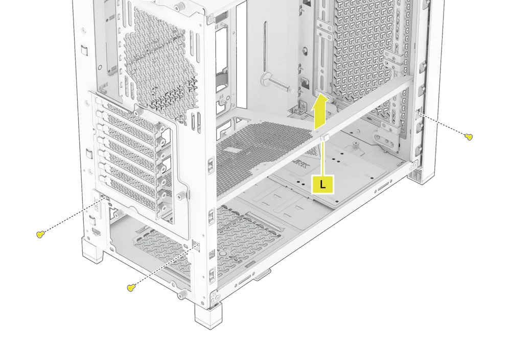
The PSU Shroud (L) is held in with a screw in the front of the case along the side and two screws in the rear panel of the case.
- Remove these three screws and the shroud will lift out.
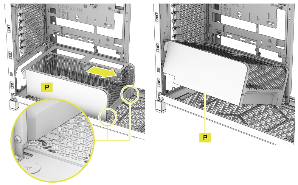
4.2 COMPACT PSU SHROUD REMOVAL
- FRAME 4000D LCD
- FRAME 4000X
- FRAME 4000D WOOD
- FRAME 4000D Vault Series
The Compact PSU Shroud (P) is held in with a screw in the front of the case along the side and two screws in the rear panel of the case.
- Remove the three screws.
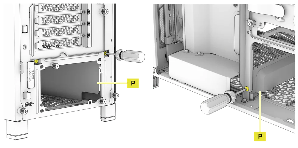
- Slide the Compact PSU Shroud (P) forward to release the clips located at its bottom front and the shroud will lift out.
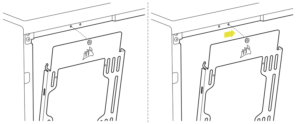
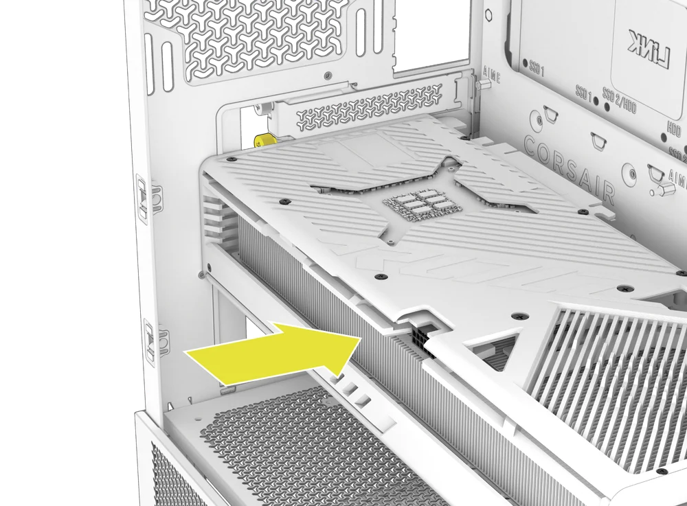
5. RETIRADA DE LA CUBIERTA DEL CABLE O DEL SOPORTE LATERAL DEL VENTILADOR
- Unscrew the screw at the top and tip the Side Fan Mounting Bracket (1) or Cable Shroud (F) out of the side. Repeat this in reverse to reinstall the part of your choice.
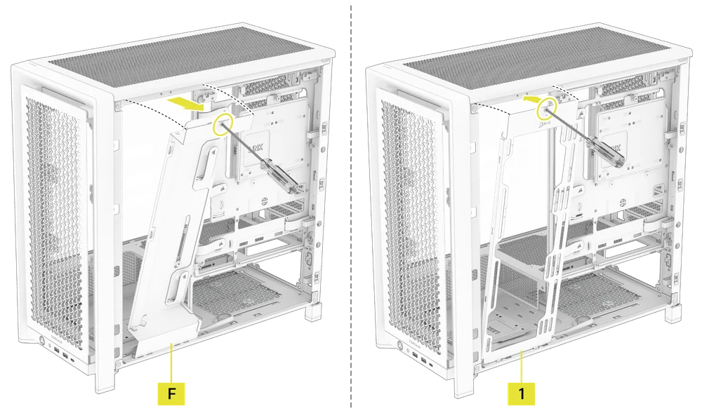
NOTE: The side mount has two positions for mounting. If using a radiator or 200mm fans, we recommend using the position closest to the motherboard.
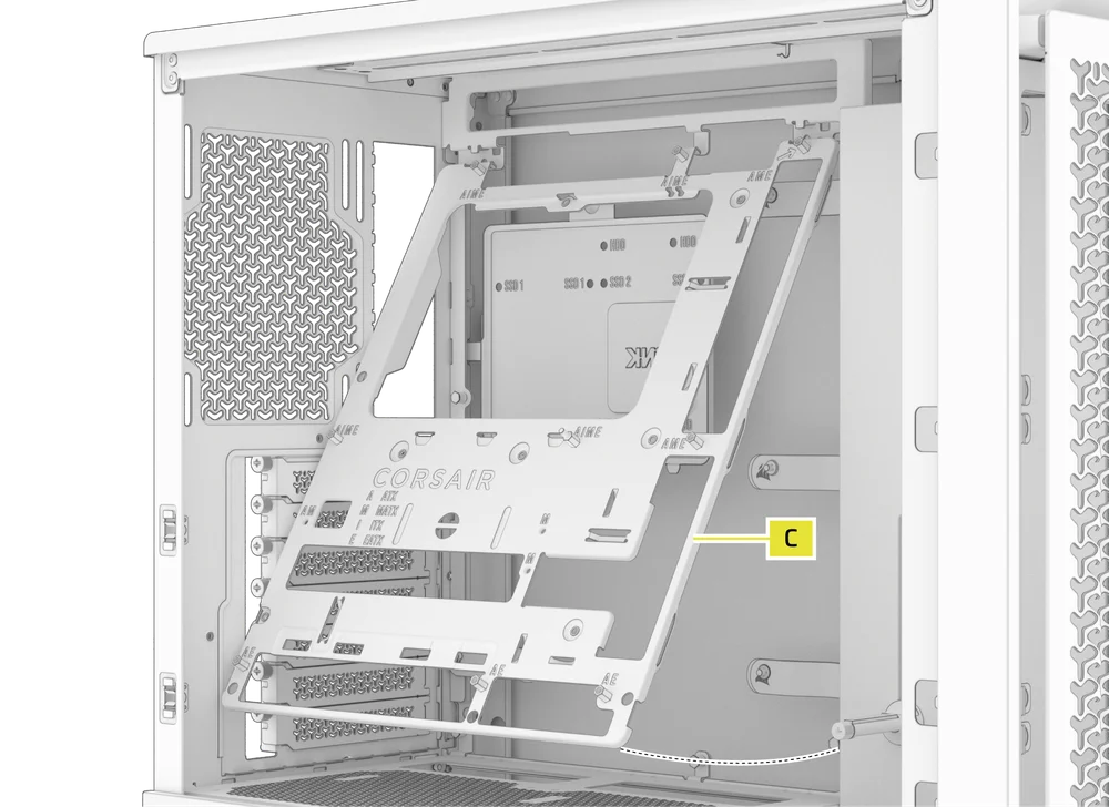
6. RETIRADA DE LA BANDEJA DE LA PLACA BASE
La bandeja estándar de acero para la placa base (C) se sujeta con 4 tornillos situados en la parte posterior de la bandeja.
- Unscrew these four screws.
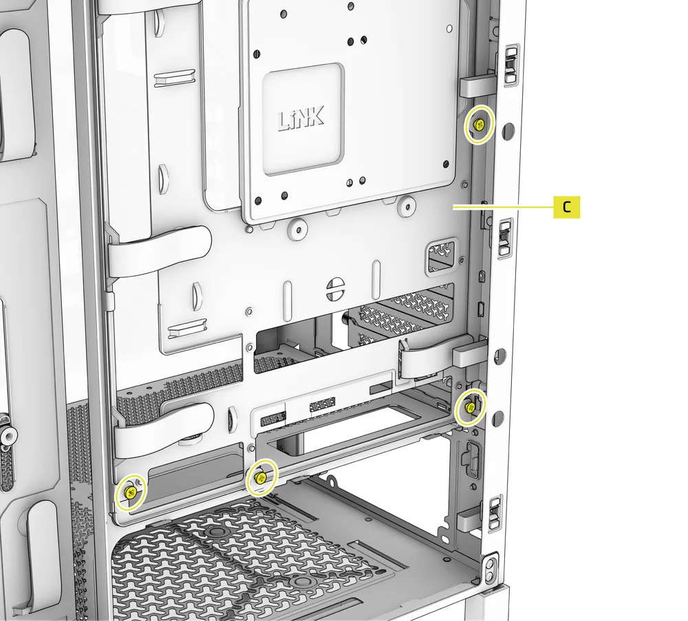
- Tilt the tray outward and lift it out.
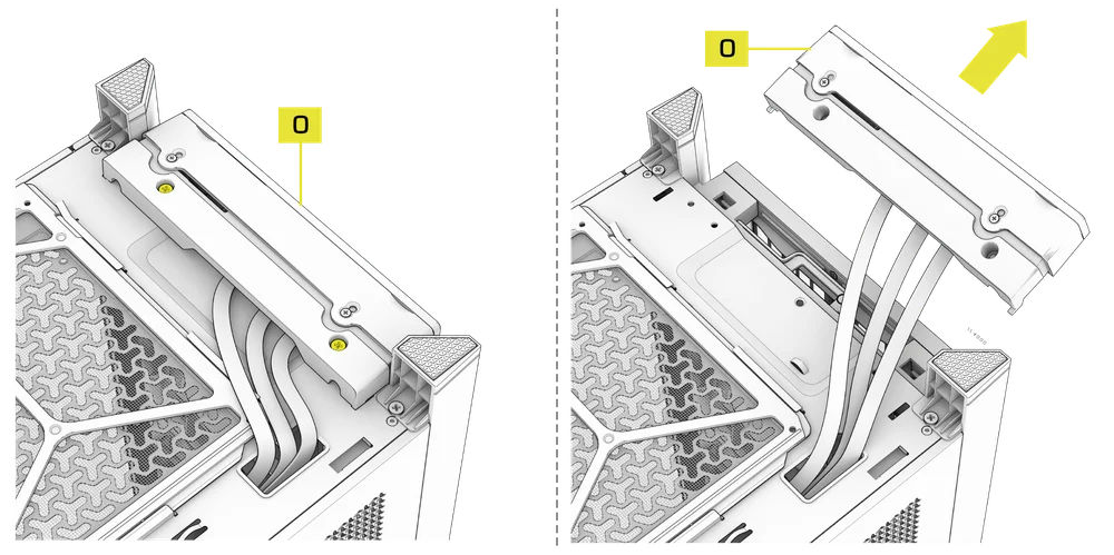
7. RETIRADA DE LAS ENTRADAS/SALIDAS DEL PANEL FRONTAL
The Front Panel I/O (O) is held in with two screws on the bottom of the case.
- To remove it, simply unscrew these two screws, and the entire Front Panel I/O (O) assembly can be lifted out.
- To reinstall the Front Panel I/O (O) or to install a new one, place the assembly back in position and secure it with the same two screws.
INSTALACIÓN DE LA PLACA BASE
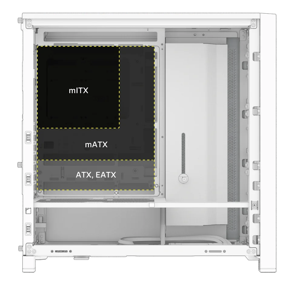
INSTALACIÓN DE LA PLACA BASE
The FRAME 4000 supports mITX, mATX, ATX, and E-ATX motherboards, including ASUS BTF, MSI Project Zero, and GIGABYTE Project Stealth with reversed connections.
- Alinee la placa base con los separadores y fíjela con los tornillos para placa base suministrados (9).
NOTA: Antes de la instalación, asegúrese de que la placa base I/O esté en su lugar, si es necesario.
CONSEJO: Si los separadores preinstalados no coinciden con los orificios de la placa base, retire los que no se utilicen y vuelva a colocarlos para que coincidan con los puntos de montaje abiertos de la placa base.
OPTIONAL MOTHERBOARD TRAY CONFIGURATIONS
The FRAME 4000 Series includes a standard motherboard tray, with additional tray options available (sold separately) to customize your build:
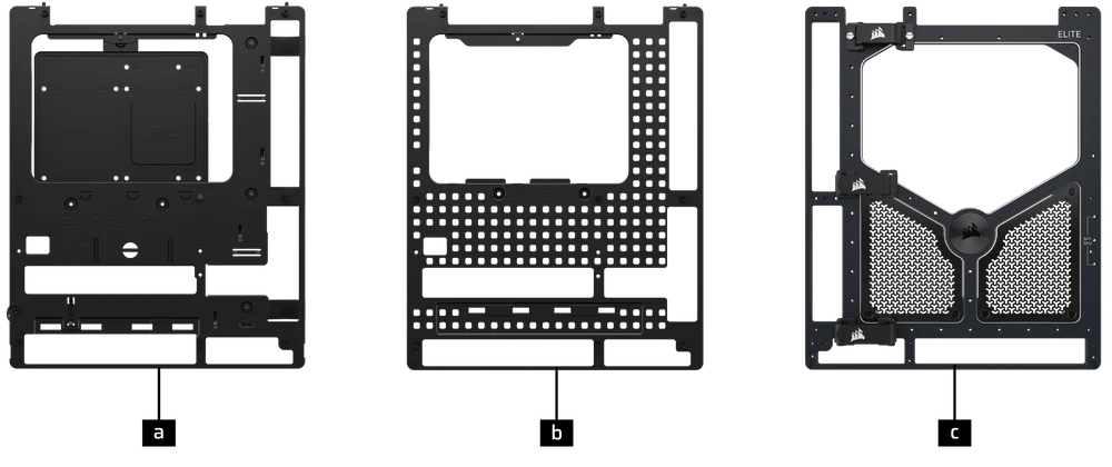
| a. FRAME Standard Steel Motherboard Tray | c. FRAME ELITE Motherboard Tray |
| b. FRAME RapidRoute 2.0 Motherboard Tray |
NOTE: FRAME ELITE motherboard tray (CNC Aluminum) is designed for use with NVMe SSDs. You will lose the HDD/SSD tray that installs on the back of the steel motherboard tray that is included with FRAME 4000 Series cases. Text for SPY & GPU on the ELITE MB Tray is to assist in assembling as a standalone test bench. Ignore text during use with FRAME 4000 Series.
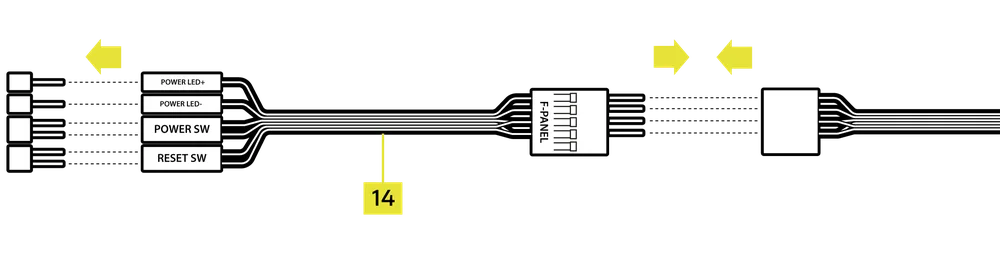
INSTALACIÓN DE CABLES DE E/S FRONTALES
1. PLACAS BASE ESTÁNDAR DE INTEL
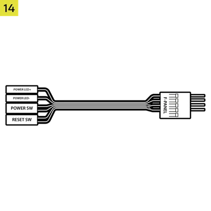
- Conecte el conector FPANEL al conector de E/S del panel frontal de la placa base, alineándolo con la disposición de las teclas. Este conector suele estar etiquetado como JFP1 en algunas placas base.
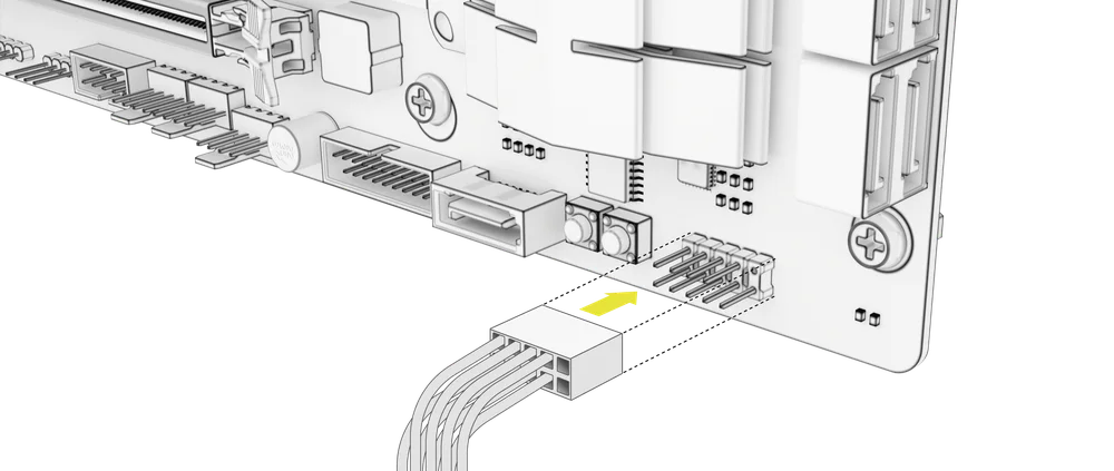
CONSEJO: Si tu PC no se enciende o presenta problemas al utilizar el conector FPANEL, prueba a utilizar el cable adaptador de E/S frontal (14) incluido para garantizar una conexión adecuada al conector de la placa base.
NOTA: Esta carcasa no incluye un LED HDD ni un interruptor de reinicio, por lo que, aunque estos conectores aparecen en el cable adaptador de E/S frontal (14), no son funcionales y se han dejado sin rellenar intencionadamente.
2. PLACAS BASE AMD O INTEL NO ESTÁNDAR
- Utilice el adaptador de E/S frontal montado en la parte superior (14) incluido para conectar el conector FPANEL a los pines del conector de E/S del panel frontal.
3. FRONT PANEL 5V ARGB CONNECTION (FRAME 4000X only)
- Run the +5V ARGB cable through the passthrough filter and into your case.
- Plug the +5V ARGB cable into your motherboard for easy ARGB control or use a COMMANDER DUO for full iCUE synchronization.
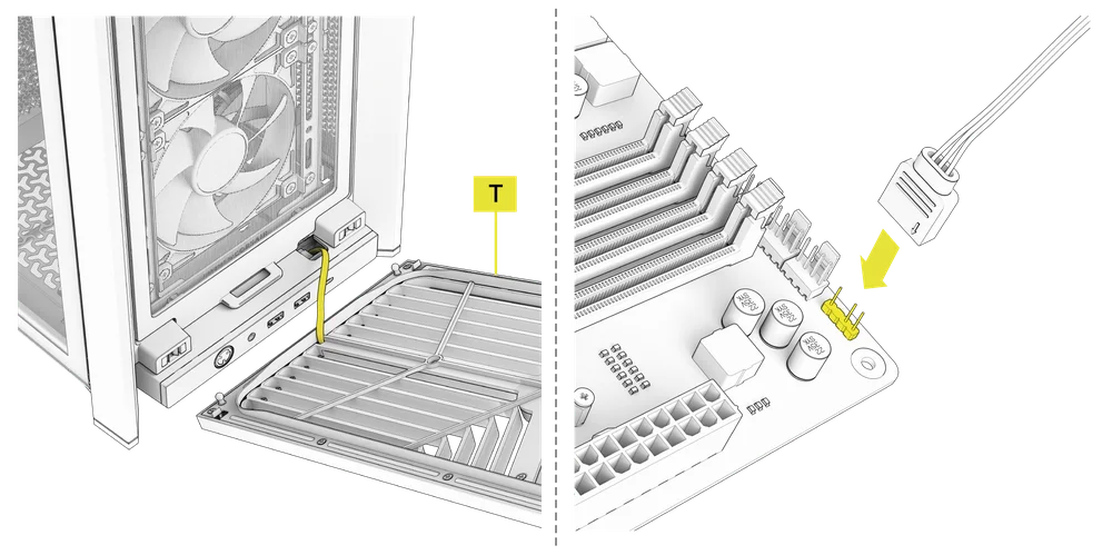
NOTE: For standard FRAME 4000D configurations without the passthrough hole in the front panel I/O, you must use the front fan filter included with the front panel and route the ARGB cable through the bottom right edge to pass it into the chassis. This wire is able to be split in half for easier routing during installation.
4. FRONT I/O EXPLANATION
- MARCO 4000D
- MARCO 4000D RS
- MARCO 4000D RS ARGB
- FRAME 4000X
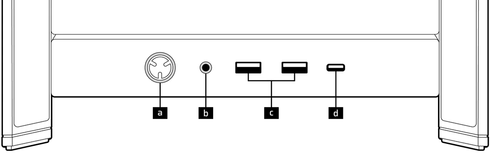
| a.Botón de encendido + LED | c.2 puertos USB 3.2 Gen 1 tipo A (5 Gbps) |
| b.Conector combinado para auriculares/micrófono | d.1 puerto USB 3.2 Gen 2x2 tipo C (20 Gbps) |
- MARCO 4000D LCD RS ARGB
- SERIE FRAME 4000D VAULT
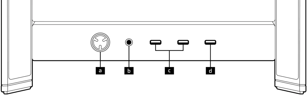
| a.Botón de encendido + LED | c. 2 puertos USB 3.2 Gen 1 tipo C (5 Gbps) |
| b.Conector combinado para auriculares/micrófono | d.1 puerto USB 3.2 Gen 2x2 tipo C (20 Gbps) |
5. FRONT I/O CONNECTIONS
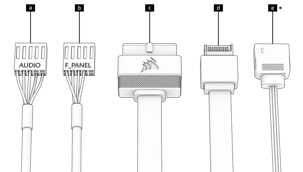
| a. HD Audio (Headphone, Microphone) | d. USB 3.2 Type-E (20 Gbps) |
| b. FPANEL (Power LED, Power Button) | e. +5V ARGB (FRAME 4000X only)* |
| c. USB 3.0 |
6. SWAPPING FRONT PANEL BUTTON POWER KEY SWITCH
The power button of the ELITE Front Panel I/O used in the FRAME 4000D LCD case utilizes a standard MX-Style key switch. This key switch is removable and replaceable to customize the look and feel of your power button.
- Simply pop off the plastic bezel on the front panel I/O and extract the key switch. Replace with a switch of your choice.
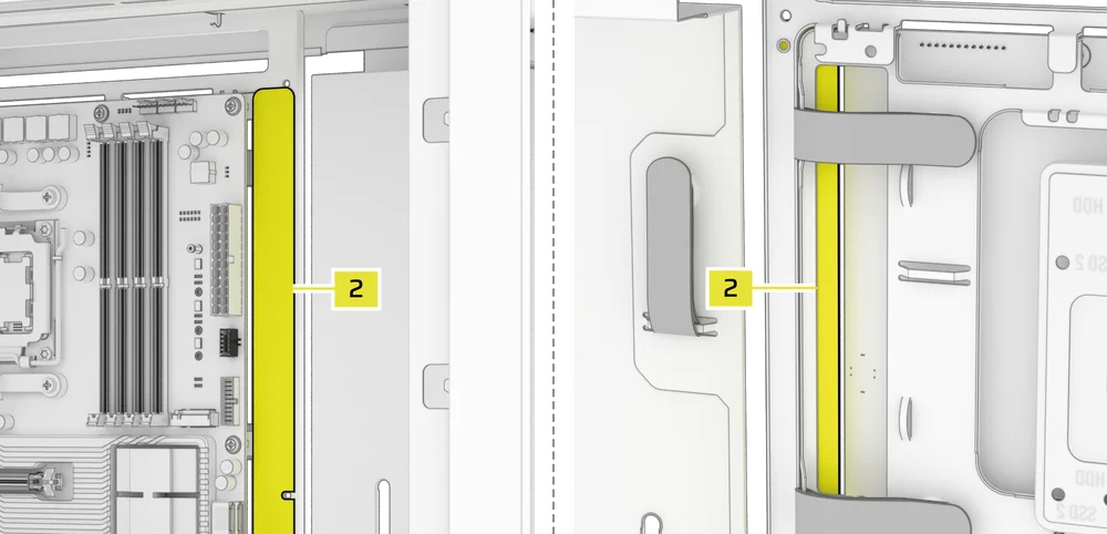
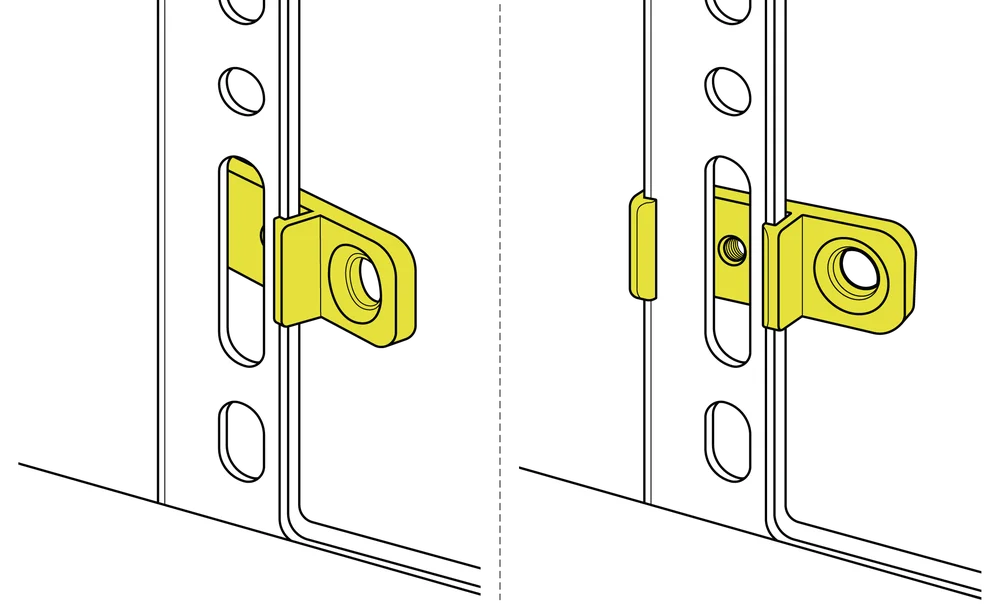
INSTALACIÓN DE LA BANDA MAGNÉTICA
El FRAME 4000 incluye una tira magnética para conectores inversos (2) diseñada para cubrir el borde visible de los orificios de los conectores inversos de la bandeja de la placa base.
- Alinee la tira magnética del conector inverso (2) con los separadores y ajústela de lado a lado para cerrar el hueco en la placa base.

1. PLACA BASE CON CONECTORES INVERTIDOS
Si va a instalar una placa base con conectores inversos, puede utilizar la tira magnética para conectores inversos (2) para rellenar el espacio alrededor del puerto ATX de 24 pines, lo que proporciona un aspecto más limpio y pulido.
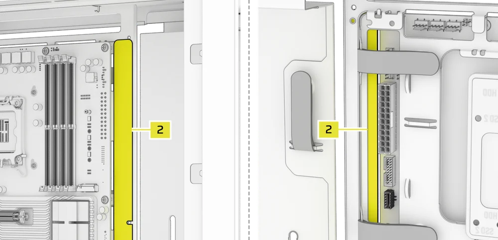
2. PLACAS BASE CON CONECTORES ESTÁNDAR
Al instalar una placa base estándar, puede deslizar la tira magnética del conector inverso (2) detrás de la placa, alineándola con los orificios de los tornillos a lo largo de la bandeja de la placa base, para cubrir la ranura del conector inverso y ocultar cualquier cable que discurra por la bandeja de la placa base, lo que le dará un aspecto más limpio.
TIP: The magnetic strip features cut-out slots, allowing you to install it simultaneously with a GPU anti-sag stabilization arm mini mount.
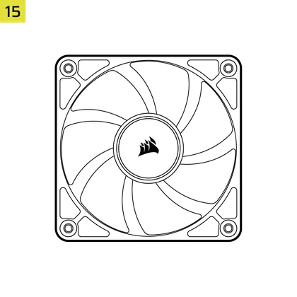
INSTALACIÓN DEL VENTILADOR
| FRAME 4000D RS/RS ARGB | ||||||
|
Front |
Top |
Rear |
Side |
PSU Shroud | Bottom | |
|
3x 120mm 2x 140mm 2x 200mm |
3x 120mm 2x 140mm
|
1x 120mm 1x 140mm
|
3x 120mm 2x 140mm
|
2x 120mm |
None |
|
|
FRAME 4000D LCD, FRAME 4000D WOOD, FRAME 4000X |
||||||
|
Front |
Top |
Rear |
Side |
PSU Shroud | Bottom | |
|
3x 120mm 2x 140mm 2x 200mm |
3x 120mm 2x 140mm
|
1x 120mm 1x 140mm
|
3x 120mm 2x 140mm
|
2x 120mm |
1x 120mm |
|
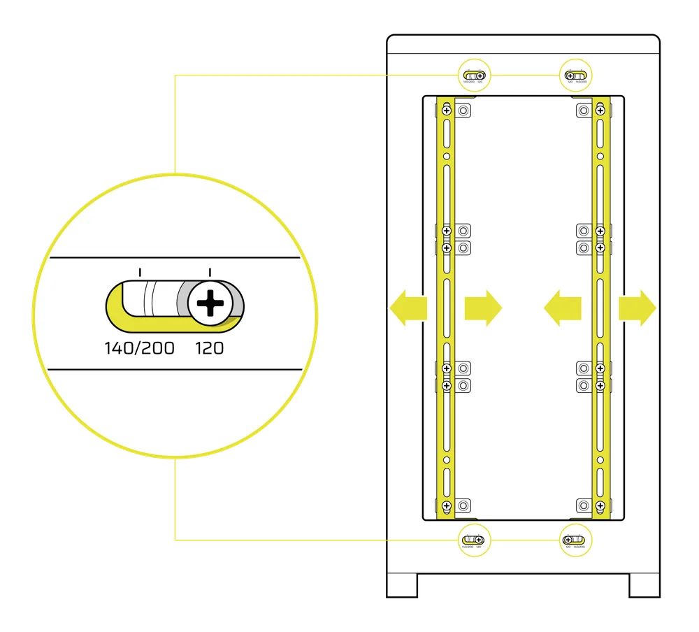
USING THE INFINIRAIL™ FAN MOUNTING SYSTEM
CORSAIR's InfiniRail™ is an innovative fan and radiator mounting system designed to offer exceptional flexibility and ease of use in PC case builds. Unlike traditional cases with fixed mounting points, InfiniRail utilizes adjustable steel rails that allow users to slide and position fans and radiators precisely where needed.
El FRAME 4000 cuenta con dos de estos sistemas InfiniRail: uno en la parte superior y otro en la parte delantera.
NOTE: Determine the size and placement of your fans before configuring the rails. You do not have to fully remove the InfiniRail Phillips head screws.
Ajuste de los rieles en la parte delantera de la carcasa
- Loosen the Phillips head screw on both ends of the InfiniRails.
- Ajuste ambos rieles frontales para sus ventiladores de acuerdo con las marcas en la carcasa.
NOTE: If using 200mm fans in front, you may need to remove the PSU shroud depending on your version of FRAME 4000 Series.
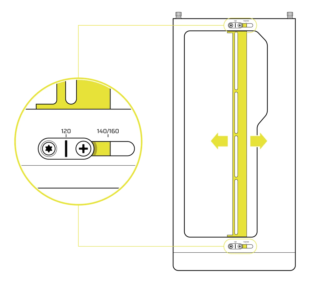
Ajuste del riel en la parte superior de la caja
- Loosen the Phillips head screw on both ends of the InfiniRail.
- Ajuste el riel superior para los ventiladores según las marcas de la carcasa.
IMPORTANTE: Los tornillos con cabezas de diseño no estándar no deben retirarse.
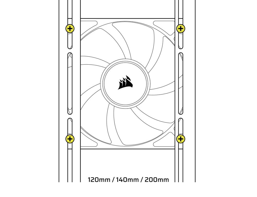
2. INSTALACIÓN DE VENTILADORES EN LA PARTE DELANTERA
Instalación de ventiladores de 120 mm o 140 mm
Para instalar ventiladores de 120 mm o 140 mm utilizando el sistema de montaje de ventiladores InfiniRail delantero, es necesario instalar los soportes para ventiladores InfiniRail (3). Utilice cuatro soportes por ventilador, dos a cada lado de los rieles.
NOTA: Algunas carcasas pueden venir con soportes para ventiladores InfiniRail preinstalados.
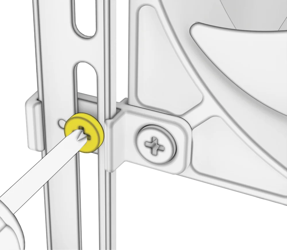
- Fije los soportes para ventiladores InfiniRail (3) a los rieles anclando primero el borde interior de cada soporte y, a continuación, encajando el borde exterior en su sitio.
- Deslice los soportes a lo largo de los rieles para alinearlos con los puntos de montaje del ventilador.
- Alinee los ventiladores con las lengüetas de montaje de los soportes y fíjelos atornillando los tornillos autorroscantes para ventiladores (7).
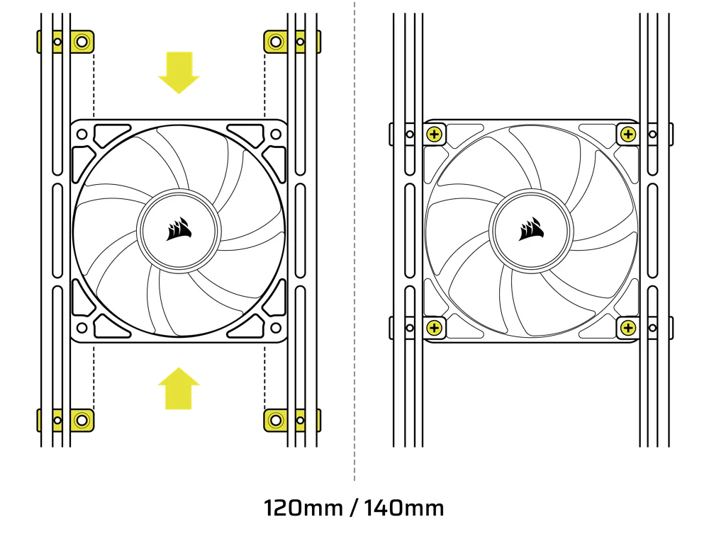
- Una vez alineado, puede fijar la configuración en su lugar con los tornillos de fijación del soporte del ventilador InfiniRail (13).
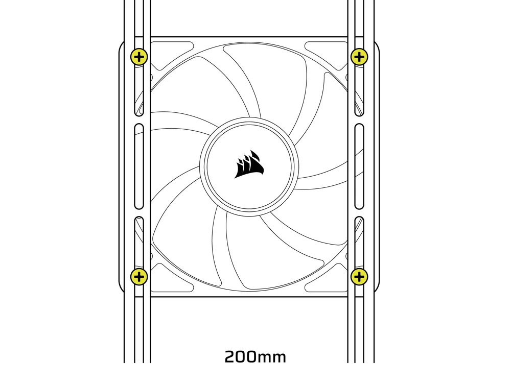
Instalación de ventiladores de 200 mm
Los ventiladores de 200 mm se atornillan directamente a los soportes InfiniRail sin necesidad de utilizar los soportes de plástico para ventiladores. Retire los soportes si vienen preinstalados en la carcasa.
- Alinee los ventiladores con las ranuras de montaje de los InfiniRails y fíjelos atornillando tornillos autorroscantes para ventiladores (7) en el marco del ventilador.
NOTA: Es posible que algunos ventiladores de 200 mm requieran retirar la cubierta de la fuente de alimentación para poder instalarlos.
NOTE: When installing 200 mm front fans, the side fan bracket or cable cover must be mounted in the secondary position (towards the motherboard tray) to provide sufficient clearance.
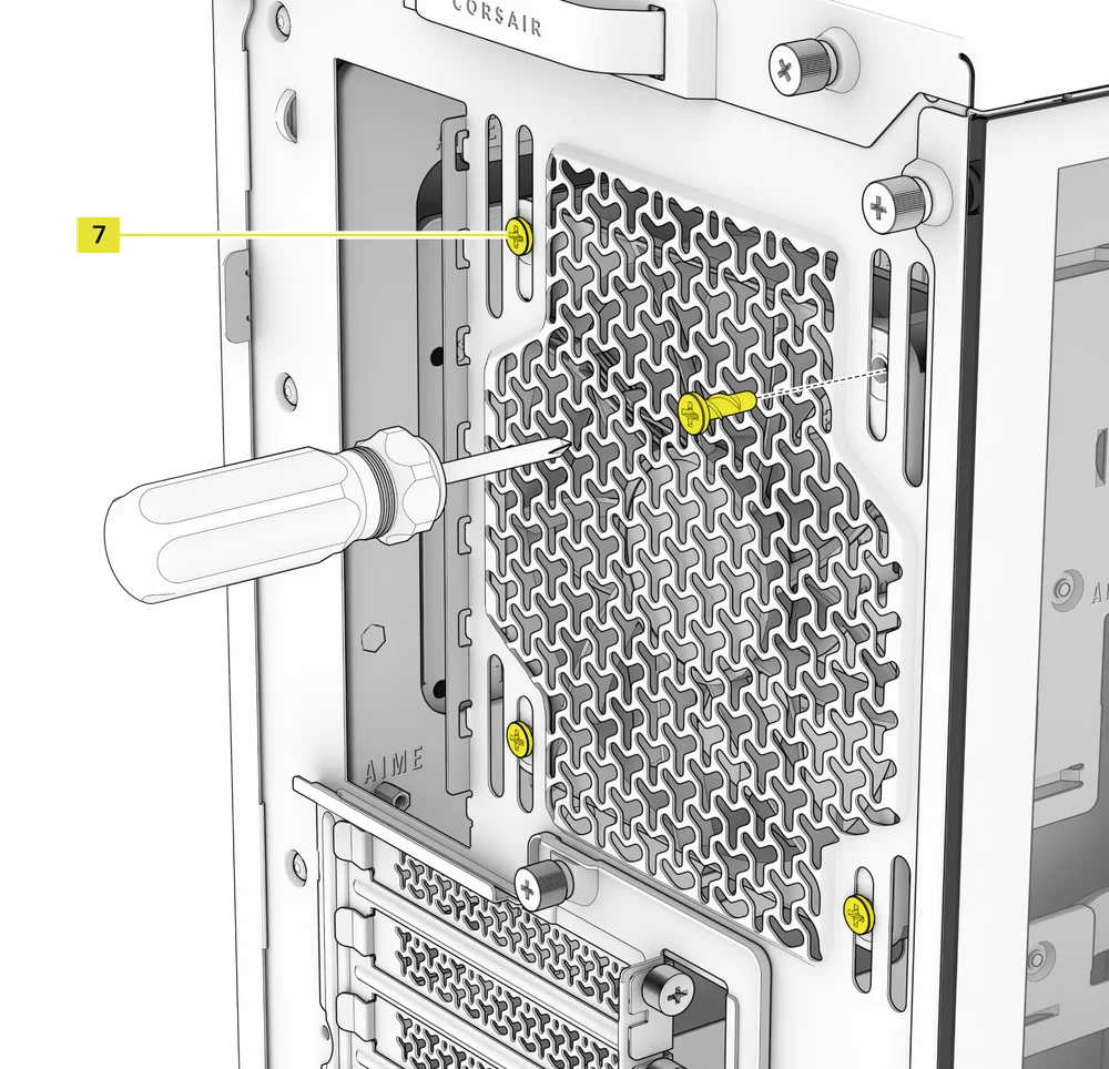
3. INSTALACIÓN DE VENTILADORES EN LA PARTE SUPERIOR
- Alinee los ventiladores con las ranuras de montaje InfiniRail y fíjelos atornillando tornillos autorroscantes para ventiladores (7) en el marco del ventilador.
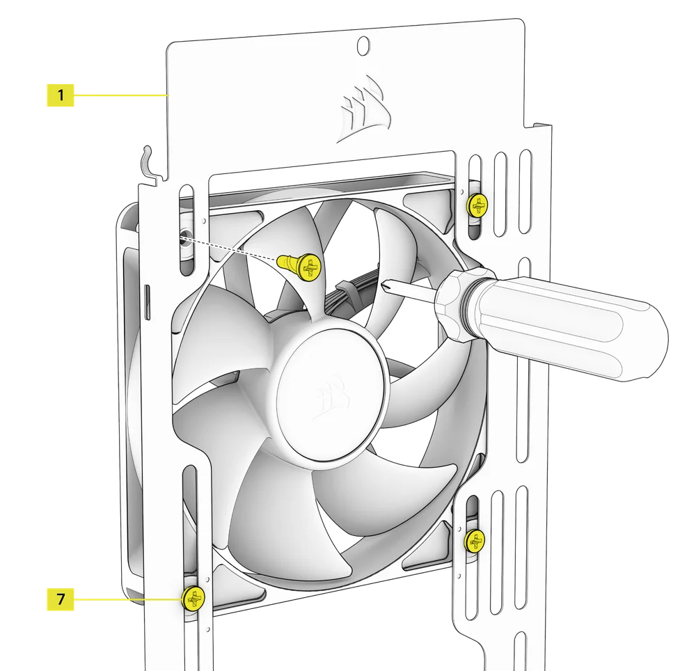
4. INSTALACIÓN DE VENTILADORES EN EL LADO
Para instalar ventiladores en el lateral, asegúrese de tener instalado el soporte de montaje lateral para ventiladores (1).
- Alinee los ventiladores con las ranuras de montaje y fíjelos atornillando los tornillos autorroscantes (7) en el marco del ventilador.
CONSEJO: Utilice los puntos marcados en el soporte de montaje lateral del ventilador (1) como guías de centrado.
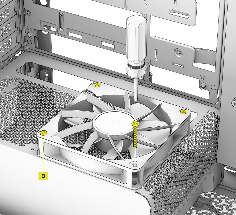
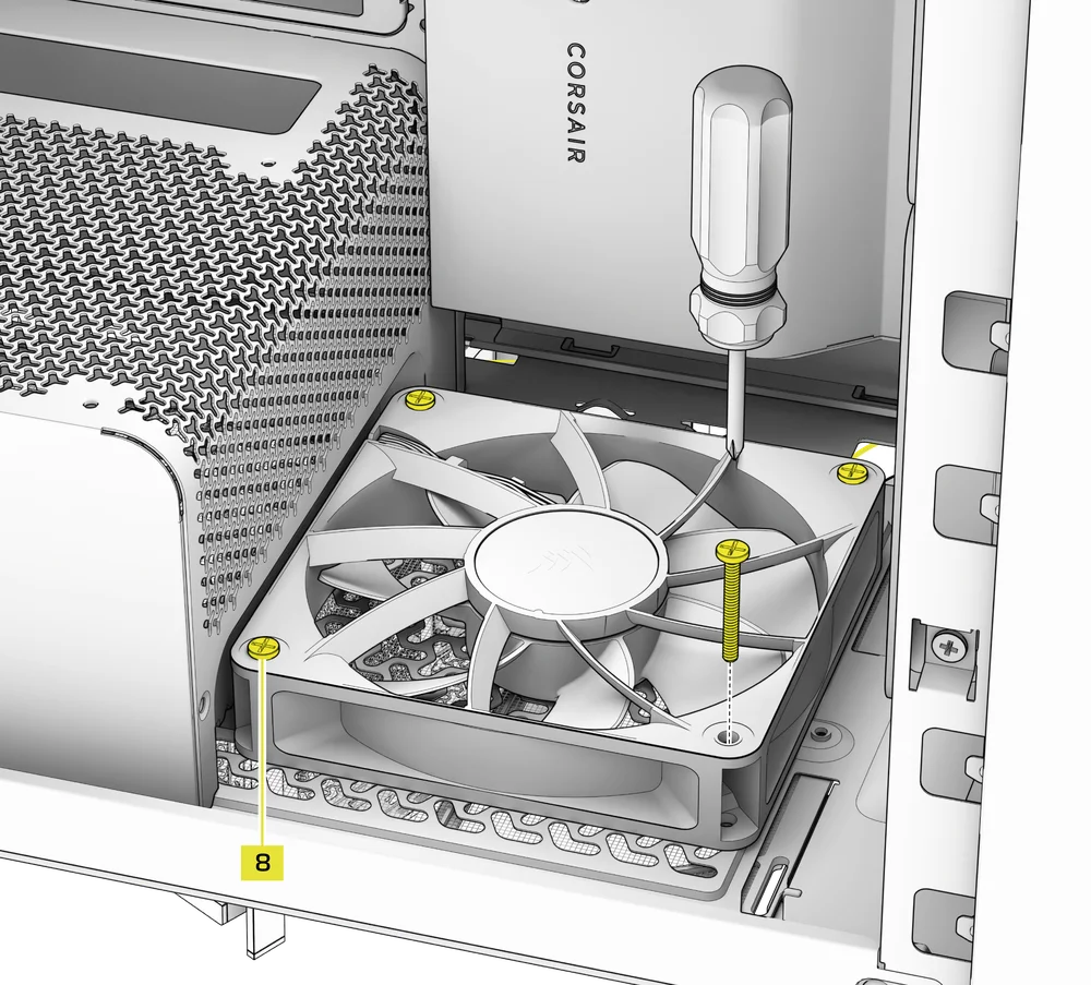
5. INSTALACIÓN DE VENTILADORES EN LA CUBIERTA DE LA FUENTE DE ALIMENTACIÓN
- Align your fans to the fan mounting holes on the PSU Shroud.
- Fije los ventiladores con tornillos largos para ventiladores (8).
6. INSTALACIÓN DE VENTILADORES EN LA PARTE TRASERA
- Alinee el ventilador con los orificios de montaje del ventilador.
- Fije el ventilador atornillando los tornillos autorroscantes para ventiladores (7).
7. INSTALLING FANS IN THE BOTTOM
- Align your fans to the fan mounting holes.
- Secure the fans with Long Fan Screws (8).
NOTE: Not all FRAME 4000 Series variants can install a bottom fan. Refer to the fan location table for your particular case.
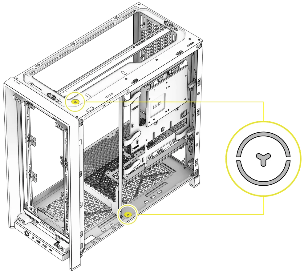
SOPORTE DE REFRIGERACIÓN PERSONALIZADO HYDRO X
The FRAME 4000 has fill / drain ports pre-punched in the top and bottom panels for a Hydro X open loop liquid cooling setup.
- Retire las tapas de los puertos haciendo palanca suavemente con un destornillador plano.
INSTALACIÓN DE RADIADORES
El FRAME 4000 ofrece varias ubicaciones para montar un radiador para refrigeración líquida, con las ubicaciones frontal y superior que cuentan con un soporte para ventilador InfiniRail ajustable. Consulte la sección Instalación del ventilador para obtener más información sobre el uso del sistema de montaje de ventiladores InfiniRail.
CONSEJO: Para obtener un rendimiento óptimo en cuanto a ruido, temperatura y fiabilidad, asegúrese de que el radiador esté montado más alto que la bomba cuando utilice un AIO.
|
Parte delantera |
Arriba |
Parte trasera |
Lateral |
Cubierta de la fuente de alimentación |
|
240 mm 280 mm 360 mm |
240 mm 280 mm 360 mm |
120 mm 140 mm |
240 mm 280 mm 360 mm |
Ninguno |
El montaje superior proporciona un rendimiento óptimo en cuanto al ruido, pero se pueden utilizar otros soportes según sus preferencias de montaje. Consulte el manual del producto de su refrigerador para obtener más consejos sobre su uso y las mejores prácticas.
1. OPTIMAL RADIATOR MOUNTING CONFIGURATION

NOTA: Para centrar el radiador, es posible que tenga que quitar uno de los tornillos de montaje del radiador. Con once tornillos seguirá habiendo suficientes puntos de montaje para instalar de forma segura el radiador y los ventiladores.
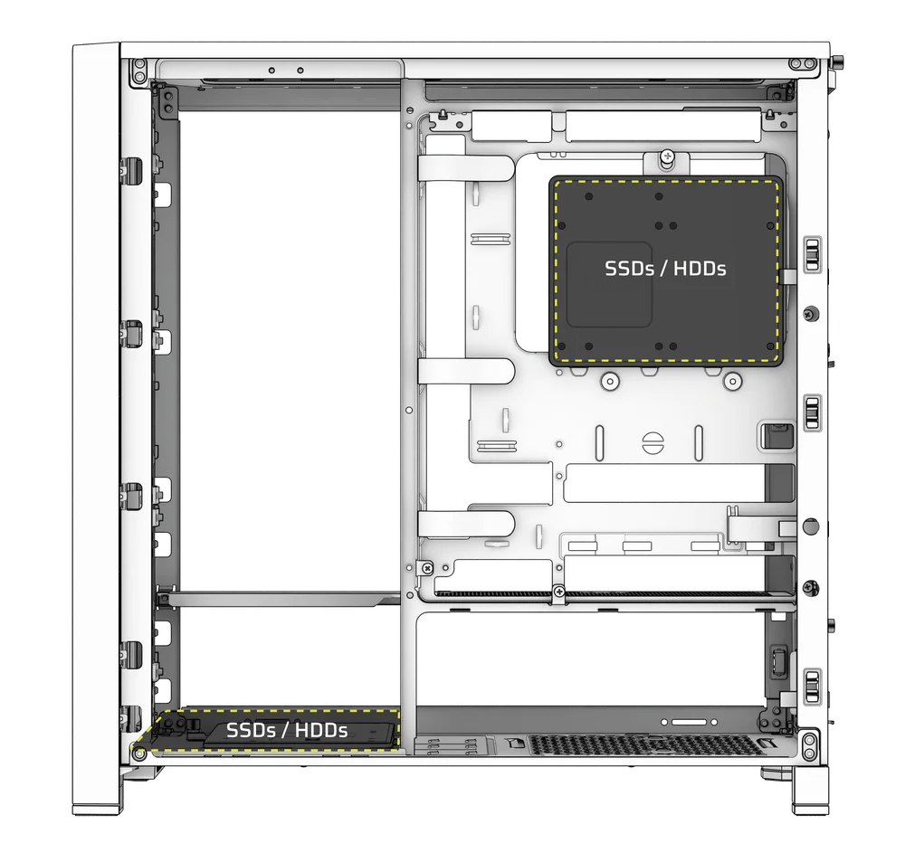
INSTALACIÓN DE DISPOSITIVOS DE ALMACENAMIENTO Y CONTROLADORES
FRAME 4000 Series cases include up to two Combination Drive Plates - with each capable of mounting one HDD or two SSDs.
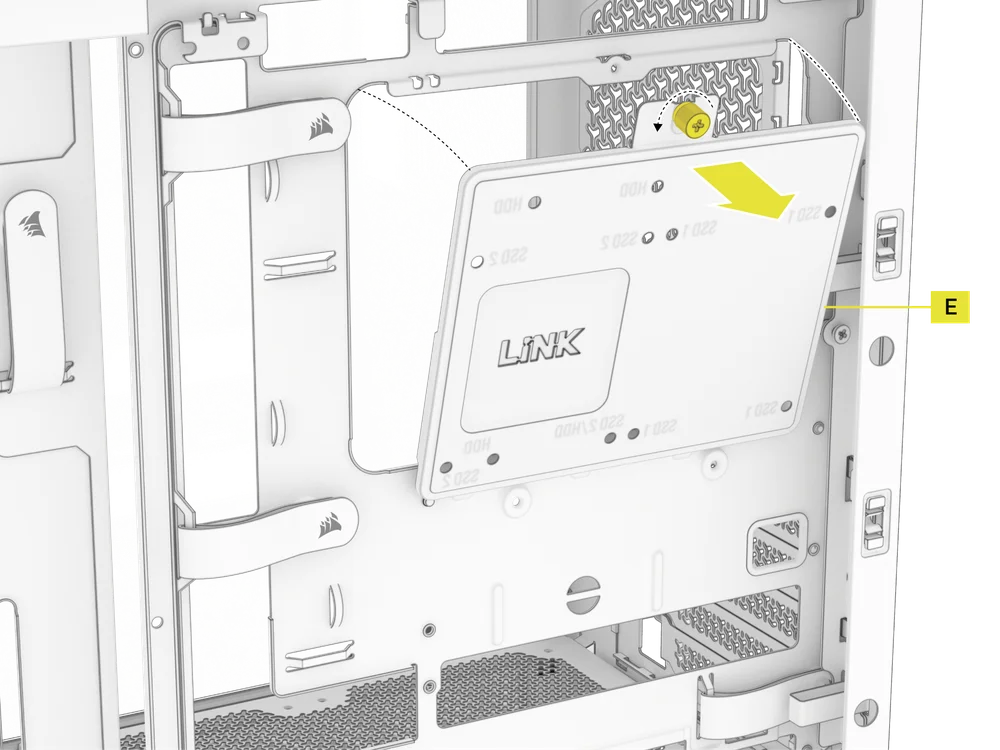
1. DESMONTAJE DE LA PLACA DE ACCIONAMIENTO COMBINADA
- Desatornille el tornillo de mariposa que sujeta la placa de accionamiento combinada (E) y, a continuación, retire la placa.
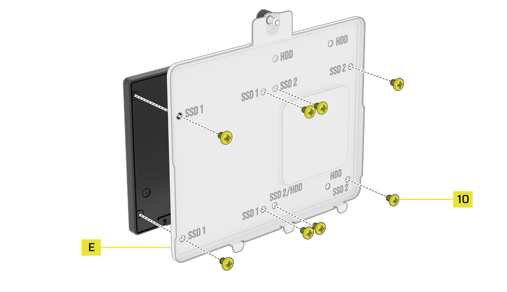
2. INSTALACIÓN DE SSD EN LA PLACA DE UNIDAD COMBINADA
- Instale la(s) unidad(es) SSD en la placa de unidad combinada (E) fijándola a la parte inferior de la placa con los tornillos SSD incluidos (10).
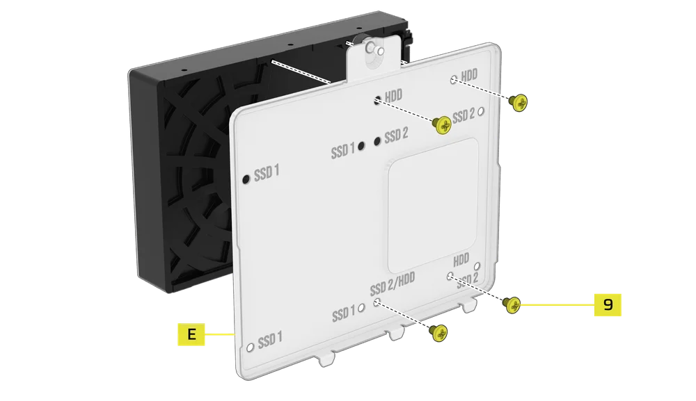
3. INSTALACIÓN DEL DISCO DURO EN LA PLACA DE LA UNIDAD COMBINADA
- Instale el disco duro en la placa de la unidad combinada (E) fijándolo a la parte inferior de la placa con los tornillos para disco duro incluidos (9).
La placa de accionamiento combinada (E) también sirve como ubicación de montaje para un controlador del concentrador del sistema iCUE LINK, si se utiliza uno.
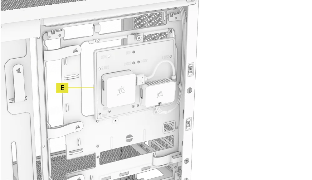
4. FIJACIÓN DE LA PLACA DE ACCIONAMIENTO COMBINADA
Vuelva a insertar la placa de accionamiento combinada (E) en su ranura designada en la carcasa y fíjela apretando el tornillo de mariposa en sentido horario.
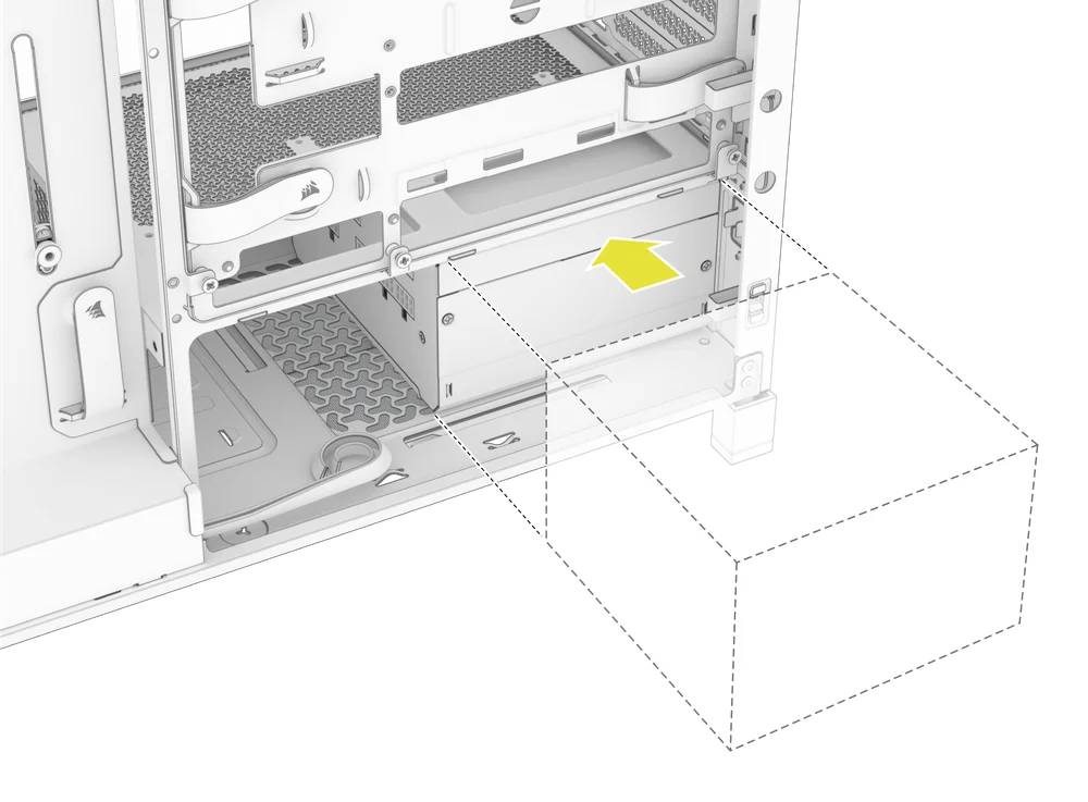
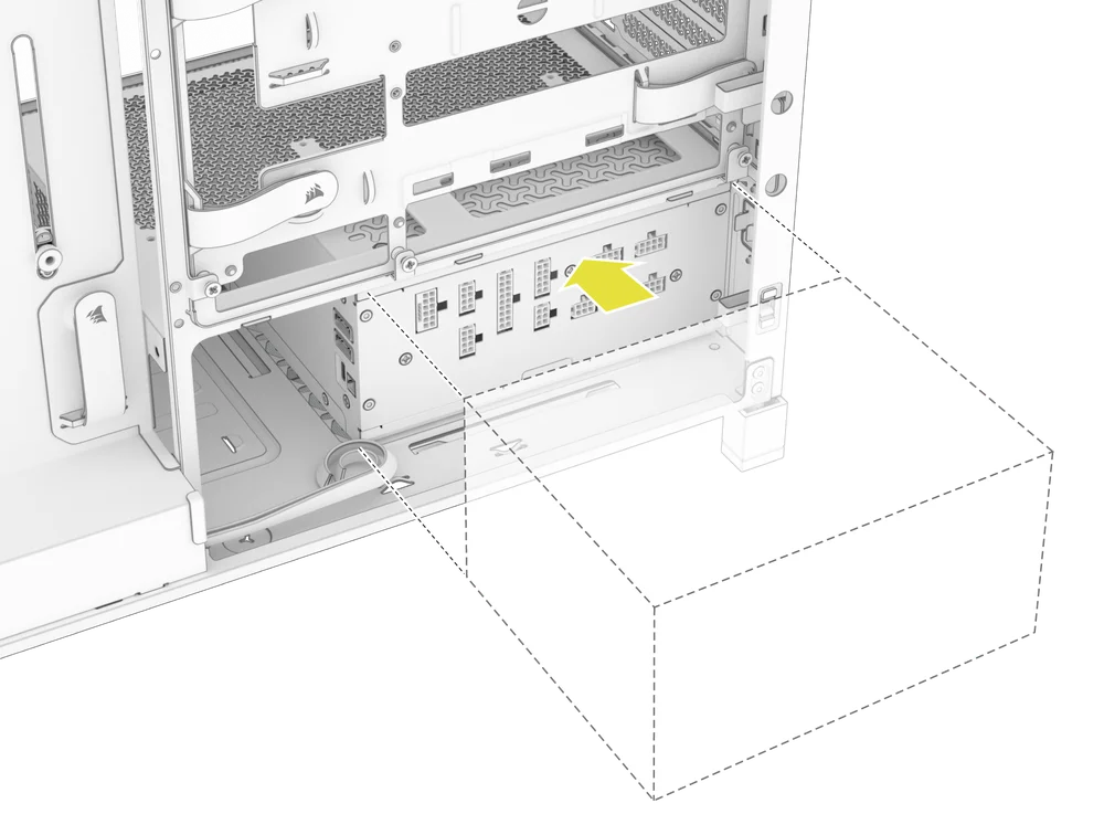
INSTALACIÓN DE SUMINISTRO ELÉCTRICO
1. INSTALACIÓN ESTÁNDAR DE LA FUENTE DE ALIMENTACIÓN
- Instale la fuente de alimentación con el ventilador hacia abajo.
- Fije la fuente de alimentación al chasis con los dos tornillos cautivos situados en la parte posterior de la carcasa.
- Para mayor seguridad, fije la fuente de alimentación con dos tornillos de placa base (9) en las esquinas del panel trasero.
2. INSTALACIÓN DE LA FUENTE DE ALIMENTACIÓN CORSAIR SHIFT
El FRAME 4000 es totalmente compatible con todas las fuentes de alimentación SHIFT y se instala de forma idéntica a una fuente de alimentación ATX estándar.
INSTALACIÓN DE LA TARJETA GRÁFICA
El soporte PCI incluido permite que el FRAME 4000 admita configuraciones de montaje de GPU tanto horizontales como verticales.
CONSEJO: Para facilitar el montaje, instala la GPU como último paso.
1. INSTALACIÓN DE UNA GPU EN ORIENTACIÓN ESTÁNDAR
- Desatornille las cubiertas de las ranuras PCIe y retírelas.
- Inserte la tarjeta en la ranura PCIe hasta que encaje en su sitio con el mecanismo de retención de la ranura PCIe.
- Alinee el soporte con las ranuras PCIe y fije la tarjeta a la carcasa.
2. USO DEL BRAZO ESTABILIZADOR ANTI-COMBA DE LA GPU
El brazo estabilizador antideslizamiento para GPU sostiene la tarjeta gráfica, evitando que se doble o se deslice bajo el peso del disipador térmico. Esto no solo ayuda a proteger la tarjeta gráfica y la ranura PCIe, sino que también contribuye a un montaje más limpio y profesional.
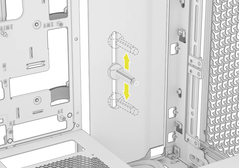
- Ajuste el brazo antideslizante de la GPU aflojando el tornillo de mariposa frontal y deslizándolo hacia arriba o hacia abajo.
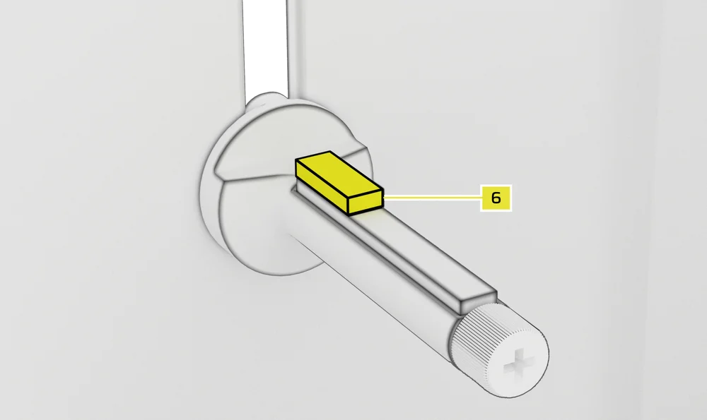
NOTA: Si el ventilador de la GPU u otras piezas entran en contacto con el brazo de goma, utilice el espaciador de goma para el brazo de estabilización antideslizante (6) incluido en la caja de accesorios para garantizar que haya espacio libre entre las piezas móviles.
- Fije el espaciador de goma autoadhesivo del brazo estabilizador antideslizamiento (6) al brazo antideslizamiento de la GPU.
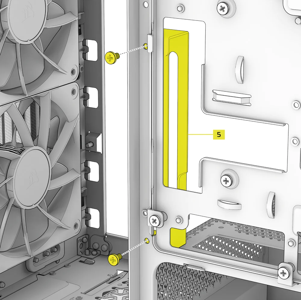
CONSEJO: Si decide cambiar la cubierta del cable (F) por el soporte de montaje lateral del ventilador (1), puede reubicar el brazo estabilizador antideslizamiento de la GPU en el mini soporte del brazo estabilizador antideslizamiento (5) y conservar la funcionalidad antideslizamiento.
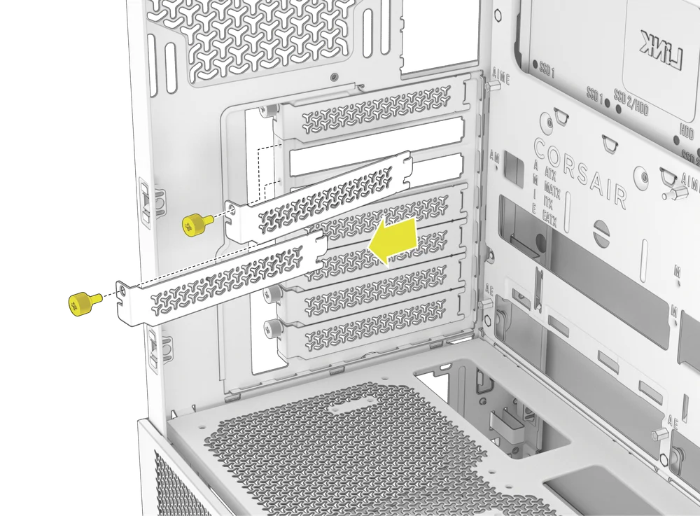
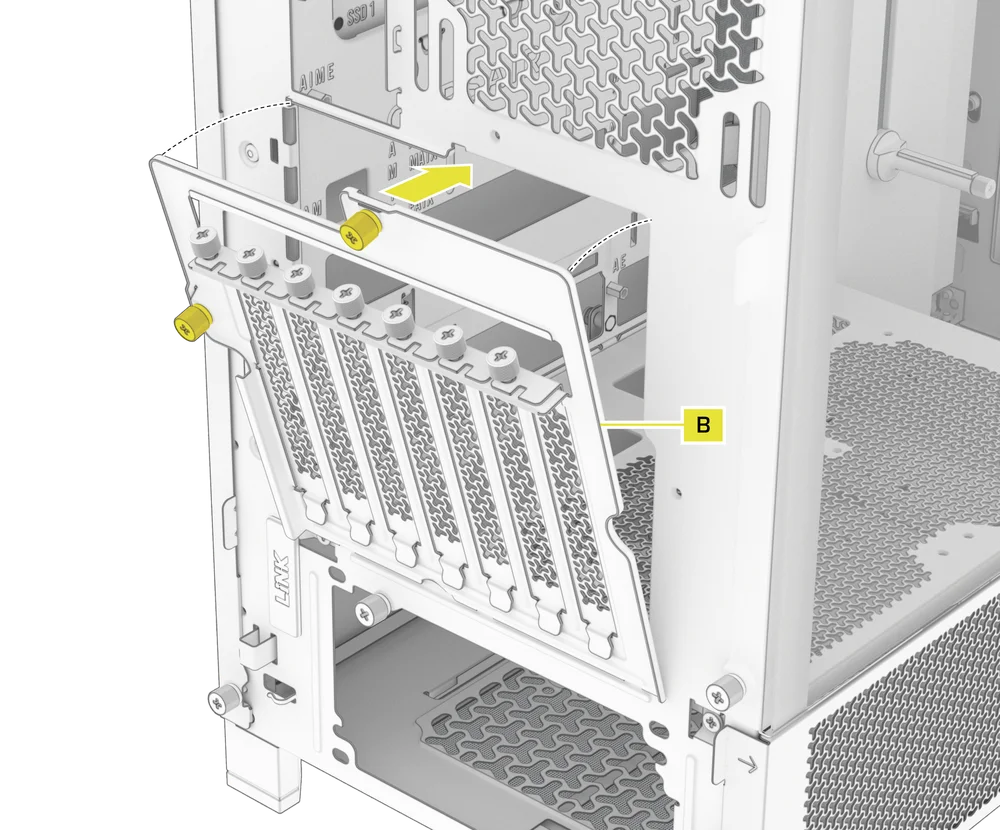
3. INSTALACIÓN DE UNA GPU EN ORIENTACIÓN VERTICAL
El FRAME 4000 admite el montaje vertical de la GPU con la placa PCI incluida (B) y una tarjeta elevadora PCIe (se vende por separado).
- Desinstale la placa PCI (B) quitando los tres tornillos de la parte trasera de la carcasa.
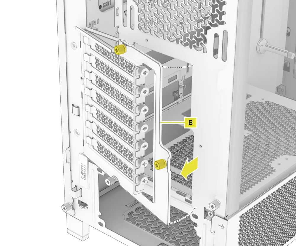
NOTA: Los tornillos de mariposa de la placa PCI son cautivos y no es necesario retirarlos por completo.
- Gire la placa PCI (B) 90 grados en sentido antihorario para que los tornillos de la cubierta de la ranura PCIe queden orientados hacia arriba.
- Vuelva a colocar la placa PCI (B) y apriete los tornillos de mariposa.
- Install the Vertical Mount Standoffs (12) from the accessory box to the top of the PSU shroud. There are two locations for standoffs, so choose the location that best suits the size of your GPU in relation to how far it is from the side panel.
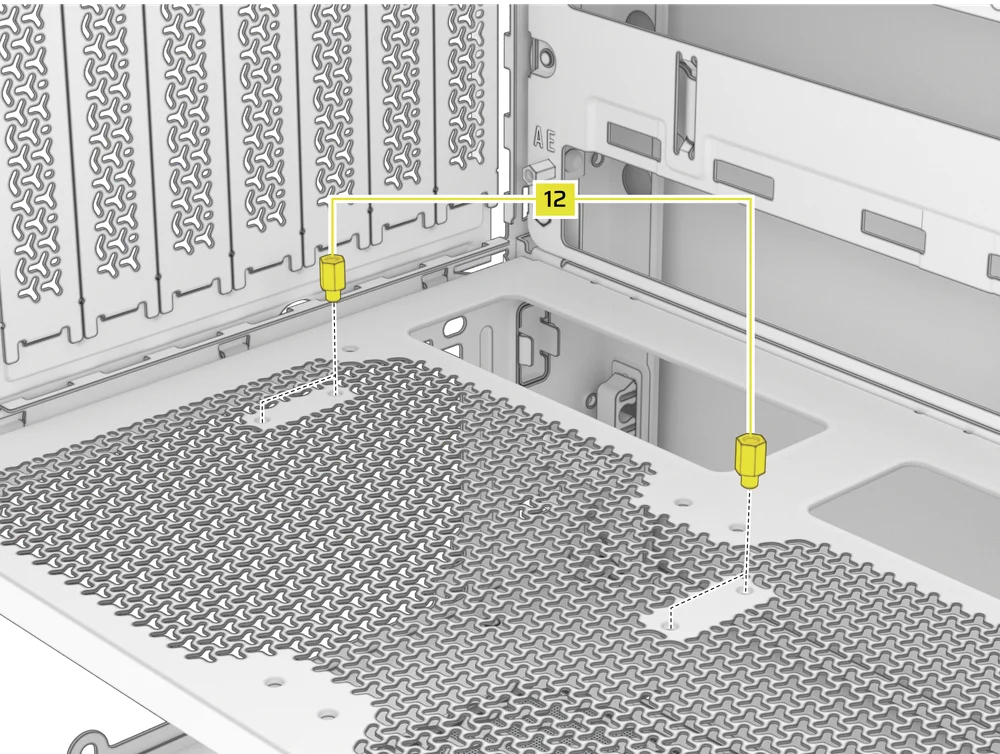
- Mount the PCIe Riser Card (sold separately) to the Vertical Mount Standoffs (12) using two of the included Motherboard Screws (9).
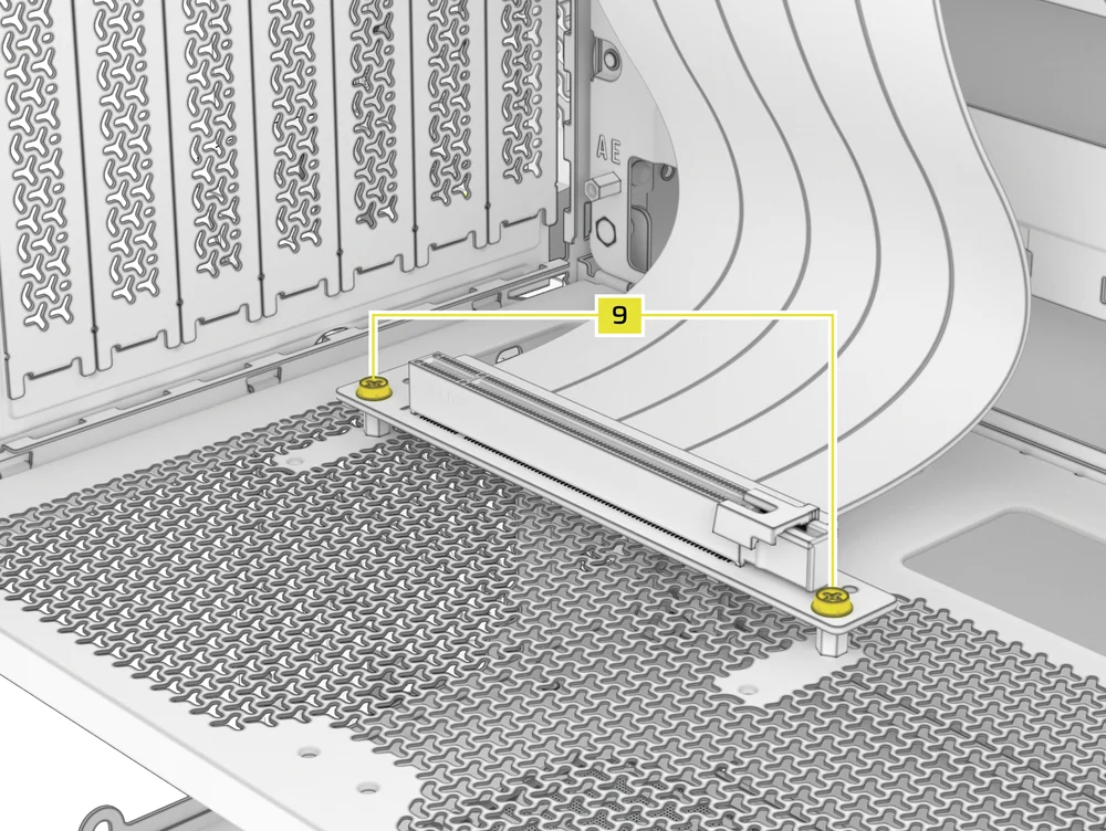
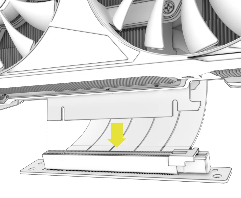
- Monte la GPU en el soporte PCI encajándola firmemente en la tarjeta elevadora hasta que encaje con un clic y, a continuación, fíjela con tornillos de mariposa.
CONECTANDO A TUS FANS
1. CONNECTING AND CONTROLLING RS FANS
- FRAME 4000D RS
- FRAME 4000D WOOD RS
- FRAME 4000X
Consulte la Guía de inicio rápido de la serie RS de CORSAIR para obtener instrucciones sobre la instalación del ventilador.
2. CONNECTING AND CONTROLLING RS ARGB FANS
- FRAME 4000D RS ARGB
- FRAME 4000D LCD RS ARGB
Consulte la Guía de inicio rápido de la serie CORSAIR RS ARGB para obtener instrucciones sobre la instalación del ventilador.
MANTENIMIENTO
1. LIMPIEZA DE LOS FILTROS DE LA CAJA
El FRAME 4000 cuenta con tres filtros de polvo extraíbles. Un filtro de alimentación en la parte inferior, un filtro magnético en el lateral y un filtro de plástico/nailon en la parte delantera.
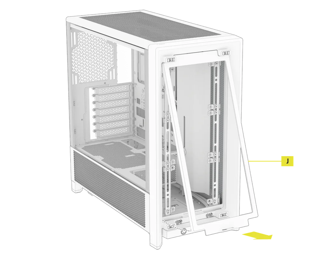
- Para retirar el filtro del ventilador delantero (J), incline el marco de plástico del filtro hacia la parte superior de la carcasa, tirando desde la parte inferior.
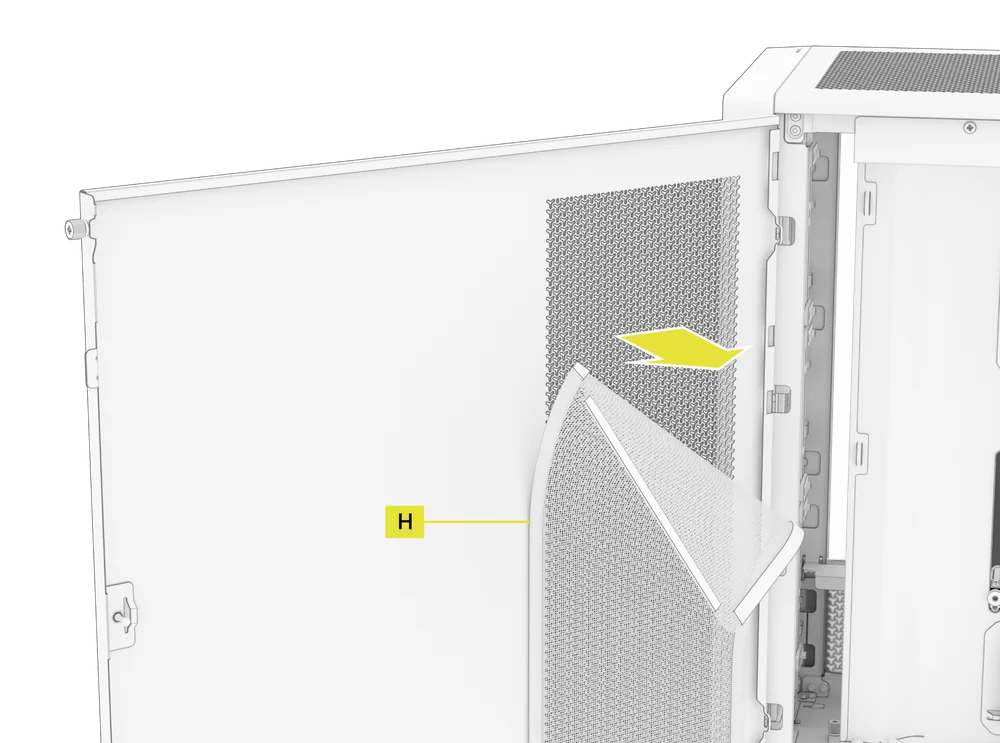
- Para retirar el filtro magnético del ventilador lateral (H), tire del centro para flexionar el marco, luego separe los extremos de los puntos de bloqueo y levante el filtro.
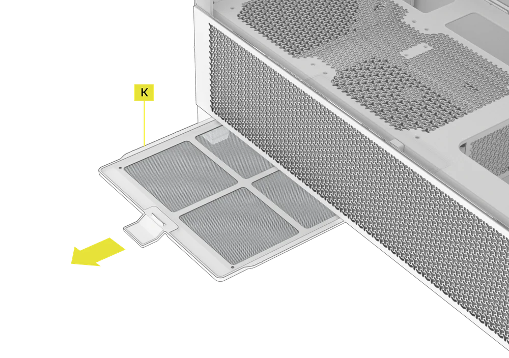
- Para retirar el filtro del ventilador de la fuente de alimentación (K), tire de él para separarlo de la carcasa.
NOTA: Los filtros se pueden limpiar con aire a presión o agua. Si enjuaga el filtro, asegúrese de que esté completamente seco antes de volver a instalarlo.
2. CONSEJOS PARA LA ORGANIZACIÓN DE LOS CABLES
El FRAME 4000 incluye otras características para la gestión de cables, tales como:
- Correas de velcro internas/externas variables para la parte trasera de la funda.
- Múltiples posiciones para correas de velcro para adaptarse a placas base con conectores estándar o inversos.
- Los puntos de sujeción con bridas están estratégicamente colocados para dirigir los cables de alimentación a dispositivos específicos.
- El cable iCUE LINK se engancha en el panel superior para sujetar de forma segura los cables LINK sin necesidad de fijarlos de forma permanente.
- Supports most reverse connector motherboards (MSI, ASUS, GIGABYTE) that feature connectors on the rear of the board for a build with no visible motherboard cables.
- Una ubicación específica para tu concentrador del sistema iCUE LINK.
- Si no te apetece dedicar mucho tiempo a organizar los cables y no quieres que se vean a través de la malla inferior del panel lateral, cambia el inserto translúcido por el inserto opaco del mismo color que se incluye en la caja de accesorios.

DECLARACIÓN DE GARANTÍA

Los chasis CORSAIR FRAME 4000 Series vienen con una garantía de 2 años.
PRODUCT CHANGES
|
January 2025 |
Initial Release |
|
March 2026 |
Thicker steel side panels 200mm fan compatibility PSU shroud cut Various case rigidity improvements |
AVAILABLE ACCESORIES
CC-8900917 FRAME 4000 3D-Y Airflow Front Panel - Black
CC-8900918 FRAME 4000 3D-Y Airflow Front Panel - White
CC-8901149 FRAME 4000 RGB FLOW Front Panel - Black
CC-8901150 FRAME 4000 RGB FLOW Front Panel - White
CC-8901151 FRAME 4000 Series WOOD Front Panel - Black/Walnut
CC-8901152 FRAME 4000 Series WOOD Front Panel - White/Oak
CC-8901153-WW FRAME 4000 Series ELITE WOOD Front Panel - Black/Walnut
CC-8901154-WW FRAME 4000 Series ELITE WOOD Front Panel - White/Oak
CC-8901155 FRAME 4000 Series Flat Glass Front Panel - Black
CC-8901156 FRAME 4000 Series Flat Glass Front Panel - White
CC-8901157 FRAME 4000 Series Pixel Glass Front Panel - Black
CC-8901158 FRAME 4000 Series Pixel Glass Front Panel - White
CC-8901208 FRAME 4000 Glass + Mesh Side Panels - Black
CC-8901209 FRAME 4000 Glass + Mesh Side Panels - White
CC-8901147 FRAME 4000 Full Tempered Glass Side Panel - Black
CC-8901148 FRAME 4000 Full Tempered Glass Side Panel - White
CC-8901048-WW FRAME 4000 Series LCD Mounting Kit - Black
CC-8901049-WW FRAME 4000 Series LCD Mounting Kit - White
CC-8901142-WW FRAME 4000 Series Cold Air Intake Kit - Black
CC-8901143-WW FRAME 4000 Series Cold Air Intake Kit - White
CC-8901171 FRAME 4000 Series - Flat Steel Panel - Black
CC-8901172 FRAME 4000 Series - Flat Steel Panel - White
CC-8900966 FRAME Standard Steel Motherboard Tray - Black
CC-8900967 FRAME Standard Steel Motherboard Tray - White
CC-8901022 FRAME RapidRoute 2.0 Motherboard Tray - Black
CC-8901023 FRAME RapidRoute 2.0 Motherboard Tray - White
CC-8901146-WW FRAME ELITE Motherboard Tray - Meteorite Aluminum
CC-8900937 FRAME 4000 Full Length PSU Shroud - Black
CC-8900938 FRAME 4000 Full Length PSU Shroud - White
CC-8901161 FRAME 4000/4500 Compact PSU Shroud - Black
CC-8901162 FRAME 4000/4500 Compact PSU Shroud - White
CC-8900919 FRAME 4000 Standard FPIO - Black (2xA; 1xC)
CC-8900920 FRAME 4000 Standard FPIO - White (2xA; 1xC)
CC-8901159-WW FRAME 4000 Series ELITE Front Panel I/O - Black (3xC + ARGB Cherry MX Style PWR Button)
CC-8901160-WW FRAME 4000 Series ELITE Front Panel I/O - White (3xC + ARGB Cherry MX Style PWR Button)
SPARE PARTS LISTING
|
CC-8900917 |
FRAME 4000D 3D-Y Airflow Front Panel, Black |
|
CC-8900918 |
FRAME 4000D 3D-Y Airflow Front Panel, White |
|
CC-8900919 |
FRAME 4000D Replacement Front I/O, Black |
|
CC-8900920 |
FRAME 4000D Replacement Front I/O, White |
|
CC-8900921 |
FRAME 4000D Replacement Front Bezel Assembly, Black |
|
CC-8900922 |
FRAME 4000D Replacement Front Bezel Assembly, White |
|
CC-8900923 |
FRAME 4000D Replacement Top Panel, Black |
|
CC-8900924 |
FRAME 4000D Replacement Top Panel, White |
|
CC-8900925 |
FRAME 4000D Replacement Three-Quarter Side Glass, Black |
|
CC-8900926 |
FRAME 4000D Replacement Three-Quarter Side Glass, Black |
|
CC-8900927 |
FRAME 4000D Replacement Y-Mesh Quarter Panel, Black |
|
CC-8900928 |
FRAME 4000D Replacement Y-Mesh Quarter Panel, White |
|
CC-8900929 |
FRAME 4000D Accessory Box, Black |
|
CC-8900930 |
FRAME 4000D Accessory Box, White |
|
CC-8900931 |
FRAME 4000D Replacement PCI Bracket, Black |
|
CC-8900932 |
FRAME 4000D Replacement PCI Bracket, White |
|
CC-8900933 |
FRAME 4000D Replacement Top InfiniRail, Black |
|
CC-8900934 |
FRAME 4000D Replacement Top InfiniRail, White |
|
CC-8900935 |
FRAME 4000D Replacement Front InfiniRail (Single), Black |
|
CC-8900936 |
FRAME 4000D Replacement Front InfiniRail (Single), White |
|
CC-8900937 |
FRAME 4000D Replacement PSU Shroud, Black |
|
CC-8900938 |
FRAME 4000D Replacement PSU Shroud, White |
|
CC-8900939 |
FRAME 4000D Replacement Drive/Controller Plate, Black |
|
CC-8900940 |
FRAME 4000D Replacement Drive/Controller Plate, White |
|
CC-8900941 |
FRAME 4000D Replacement Cable Cover, Black |
|
CC-8900942 |
FRAME 4000D Replacement Cable Cover, White |
|
CC-8900943 |
FRAME 4000D Replacement InfiniRail Fan Mounts (12pcs), Black |
|
CC-8900944 |
FRAME 4000D Replacement InfiniRail Fan Mounts (12pcs), White |
|
CC-8900945 |
FRAME 4000D Replacement Strap Kit, Black |
|
CC-8900946 |
FRAME 4000D Replacement Strap Kit, White |
|
CC-8900947 |
FRAME 4000D Replacement PSU Filter, Black |
|
CC-8900948 |
FRAME 4000D Replacement PSU Filter, White |
|
CC-8900949 |
FRAME 4000D Replacement Front Filter, Black |
|
CC-8900950 |
FRAME 4000D Replacement Front Filter, White |
|
CC-8900951 |
FRAME 4000D Replacement Side Filter, Black |
|
CC-8900952 |
FRAME 4000D Replacement Side Filter, White |
|
CC-8900953 |
FRAME Series GPU Anti-Sag Assembly, Black |
|
CC-8900954 |
FRAME Series GPU Anti-Sag Assembly, White |
LEGAL
©2026 CORSAIR MEMORY, Inc. All rights reserved. CORSAIR and the sails logo are registered trademarks of CORSAIR in the United States and/or other countries. All other trademarks are the property of their respective owners. Product may vary slightly from those pictured.
CONTENIDO RELACIONADO


