MANUAL | QUICK START GUIDE
CORSAIR COMMANDER DUO
LIGHTING AND FAN CONTROLLER – ARGB AND iCUE LINK HYBRID
GETTING TO KNOW YOUR COMMANDER DUO
PACKAGE CONTENTS
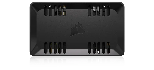
1x COMMANDER DUO
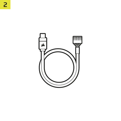
1x USB Cable
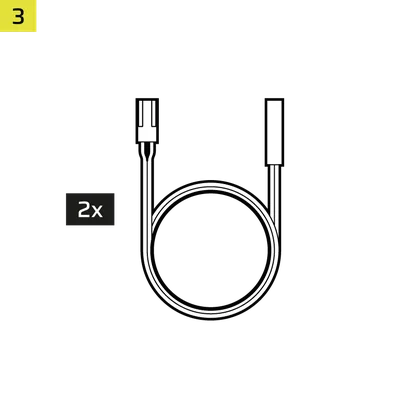
2x Temperature Sensors
2x iCUE LINK Bridge Connectors
2x Double-sided Tape
PREREQUISITES
*Sold separately
iCUE LINK System Hub
(not needed for ARGB mode)
iCUE Version 5 or Higher
Microsoft Windows 11 or Higher
ARGB MODE VS LINK MODE
The COMMANDER DUO supports standard PWM fan speed and standard ARGB device (fans and strips) control through its default USB connection with iCUE (ARGB MODE).
If you have an iCUE LINK System Hub you can use the COMMANDER DUO in LINK MODE. This will allow you to remove the USB cable and SATA power cable and use the power and data from the iCUE LINK System Hub to control the standard PWM fan speed and standard ARGB devices connected to the COMMANDER DUO.
ARGB MODE
In ARGB mode, you can daisy-chain up to 12 fans across two channels, with each channel supporting six fans on the COMMANDER DUO. Each channel's fans are managed as a group within the iCUE software.
LINK MODE
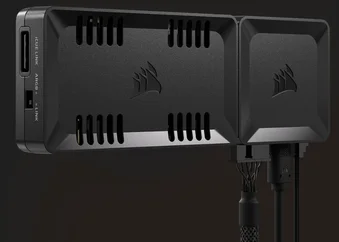
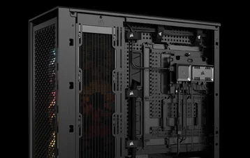
When using iCUE LINK devices, simply dock the System Hub to one side of the COMMANDER DUO and switch to LINK mode. This configuration allows the System Hub to take control over all connected devices via iCUE, and the COMMANDER DUO no longer requires SATA power.
INSTALLATION
1. CONNECT FAN CABLES AND TEMPERATURE SENSORS
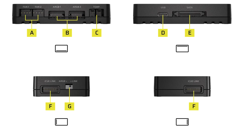
- Connect the 4-pin PWM fan cable to one of the 4-Pin PWM Fan Headers (A).
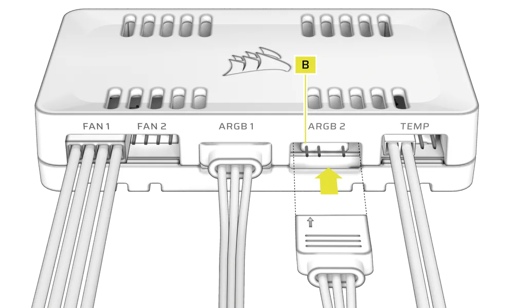
- Connect the 3-pin ARGB cable to one of the 3-Pin ARGB Headers (B).
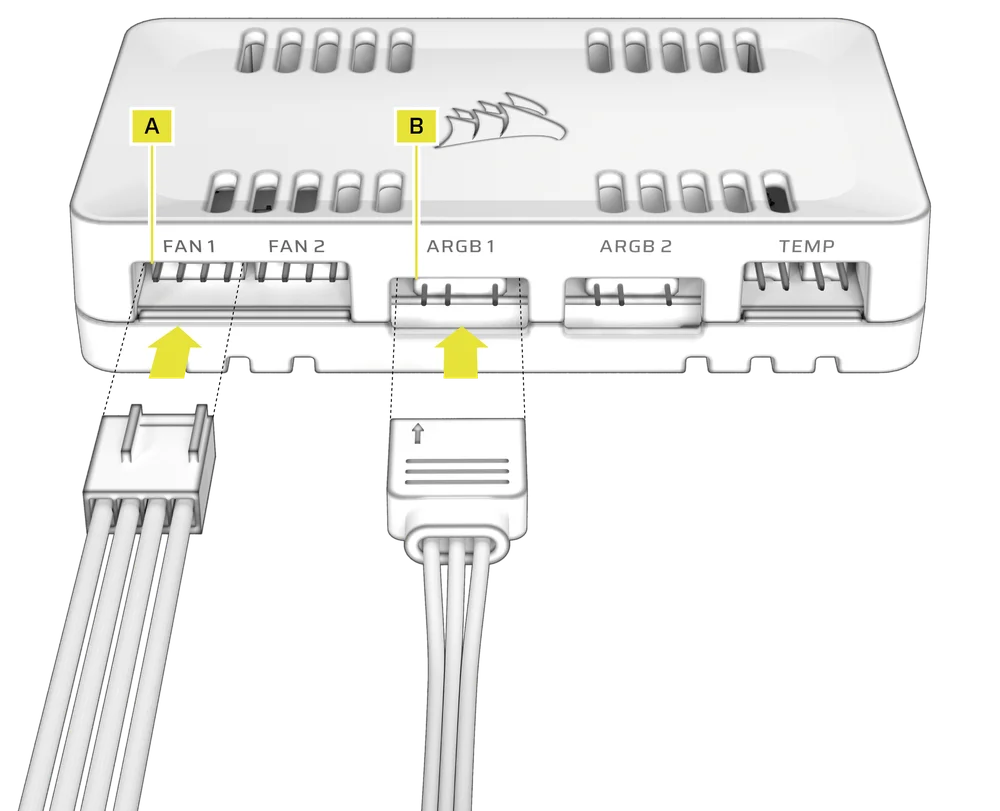
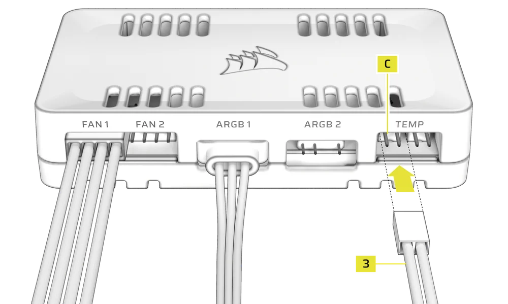
- Connect a temperature sensor (3) to one of the 2-pin Temperature Sensor Headers (C) (Optional).
(Left header: Channel 1, Right header: Channel 2)
2. CONNECT OPTIONAL CORSAIR ACCESSORIES
- Connect CORSAIR Hydro X components to one of the 3-Pin ARGB Headers (B).
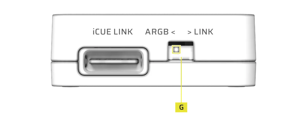
3. ENABLE ARGB FAN CONTROLLER MODE
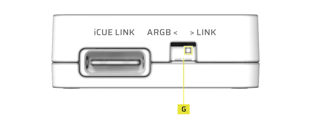
- Flip the Toggle Switch (G) on the left side of the controller to the left position to enable ARGB Fan Controller Mode.
4. CONNECT THE COMMANDER DUO TO THE USB HEADER AND POWER CONNECTION
- Connect the USB Cable (2) into the USB Port (D) of the controller.
- Connect the SATA power cable from the power supply to the SATA Power Connector (E) of the controller.
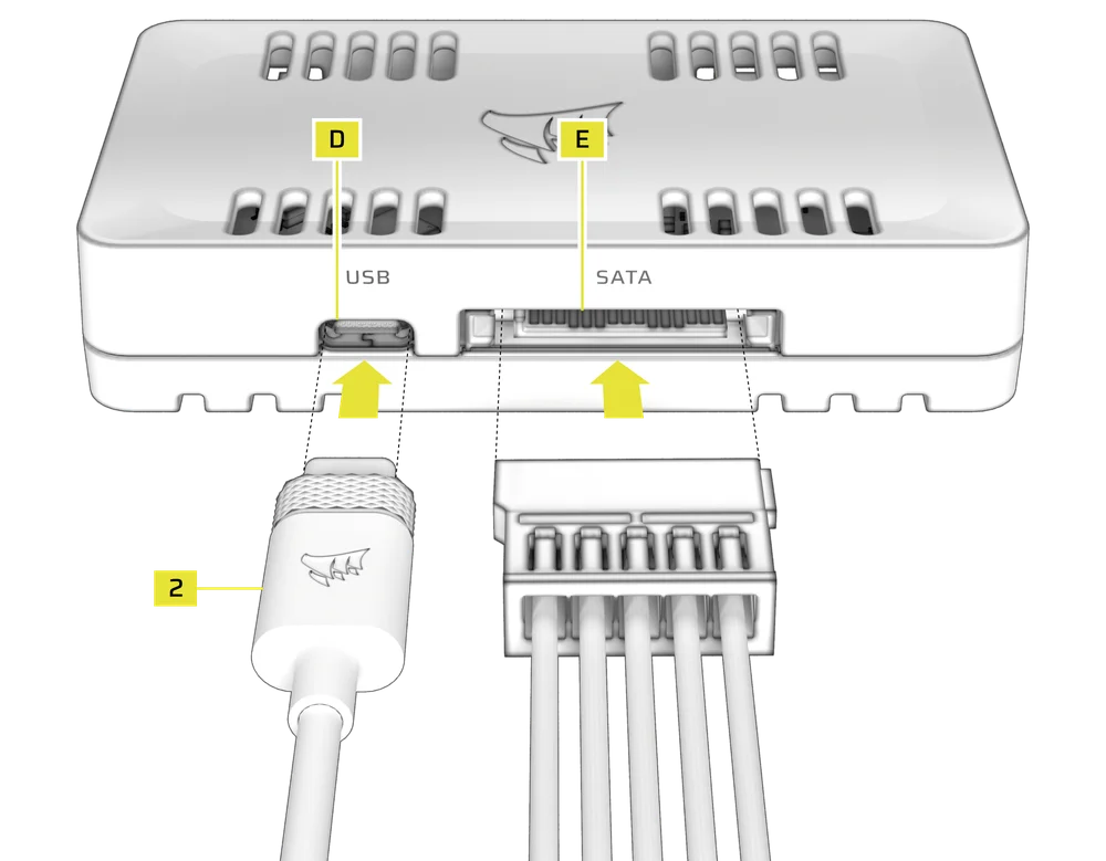
- Connect the 9-pin USB 2.0 connector of the USB Cable (2) into a USB 2.0 header on the motherboard.

5. ENABLE LINK MODE FOR iCUE LINK DEVICES
- Flip the Toggle Switch (G) on the left side of the controller to the right position to enable LINK Mode.
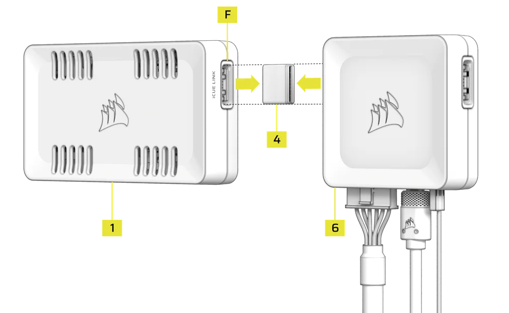
- Use the iCUE LINK Bridge Connector (4) to link one of the COMMANDER DUO’s iCUE LINK Ports (F) to the iCUE LINK System Hub (6).
You can use the iCUE LINK port on either side of the System Hub (6) and COMMANDER DUO (1).
6. CONNECT iCUE LINK DEVICES
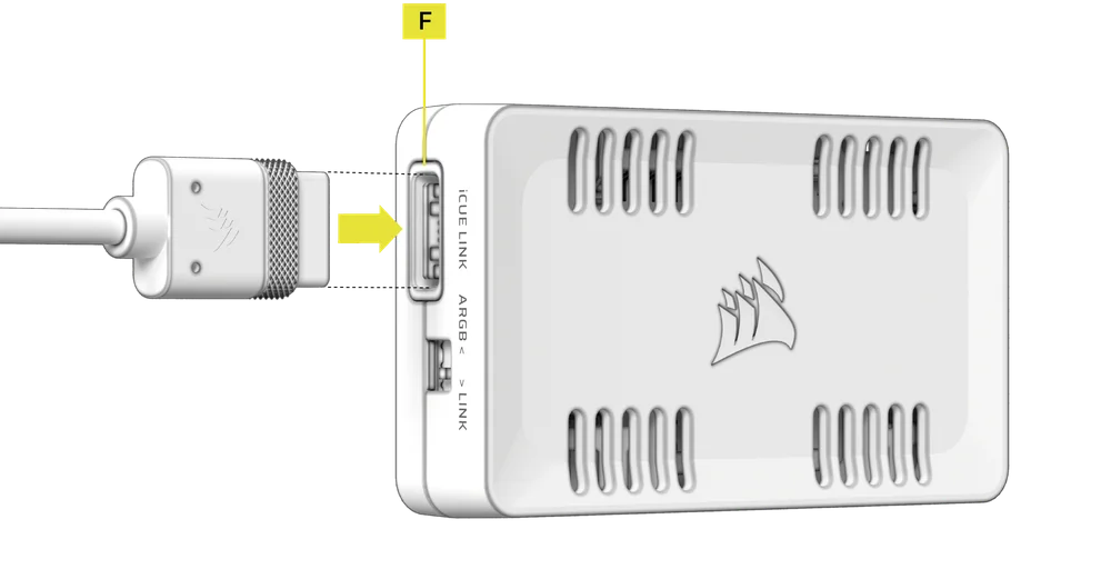
- Connect iCUE LINK devices to a remaining iCUE LINK Port (F) on the COMMANDER DUO.
The COMMANDER DUO acts as an extension of the iCUE LINK System Hub (6).
7. LINK MODE DEVICE COUNT
|
Combination |
Device Count |
|
FAN1 Only |
1 Device |
|
FAN2 Only |
1 Device |
|
FAN1 + FAN2 |
2 Devices |
|
ARGB1 Only |
1 Device |
|
ARGB2 Only |
1 Device |
|
ARGB1 + ARGB2 |
2 Devices |
|
FAN1 + ARGB1 |
1 Device |
|
FAN2 + ARGB2 |
1 Device |
|
FAN1 + FAN2 + ARGB1 |
2 Devices |
|
FAN1 + FAN2 + ARGB2 |
2 Devices |
|
FAN1 + FAN2 + ARGB1 + ARGB2 |
2 Devices |
|
TEMP1 |
1 Device |
|
TEMP2 |
1 Device |
|
TEMP1 + TEMP2 |
2 Devices |
- After connecting all devices, refer to the CORSAIR System Hub Quick Start Guide for detailed installation instructions.
SOFTWARE SETUP
1. INSTALL iCUE
- Download and install the latest version of iCUE from www.corsair.com/downloads
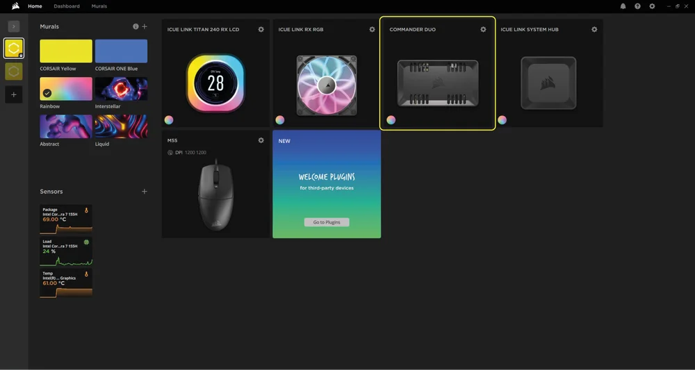
Once iCUE is installed, run the software. The COMMANDER DUO will appear in the iCUE interface. When using COMMANDER DUO in LINK Mode, iCUE will also display all the connected devices.
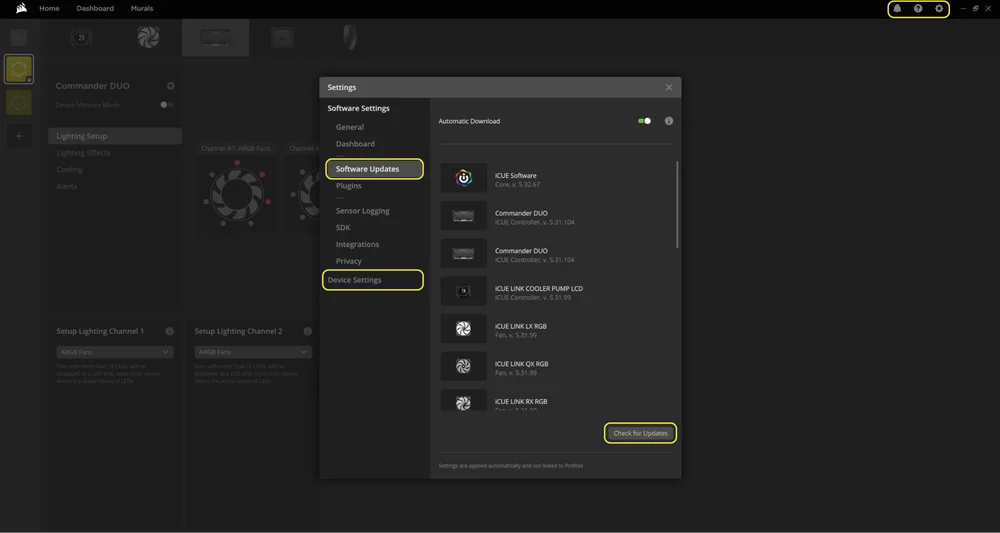
2. CHECK FOR UPDATES
If any of the connected devices need a firmware update, you will be prompted to perform an update via a notification in the top right corner. You can also click the settings (cog wheel icon in the top right corner) to check for software updates manually. To update the firmware, click “Device Settings” from the same menu.
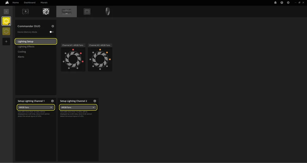
3. LIGHTING SETUP
The Lighting Setup page will display the devices connected to the COMMANDER DUO's ARGB headers. Each header (channel) will show only one device icon.
- Select "Lighting Setup" in the main menu on the left.
- Use the dropdown menu in the bottom panels to select the type of device you have connected.
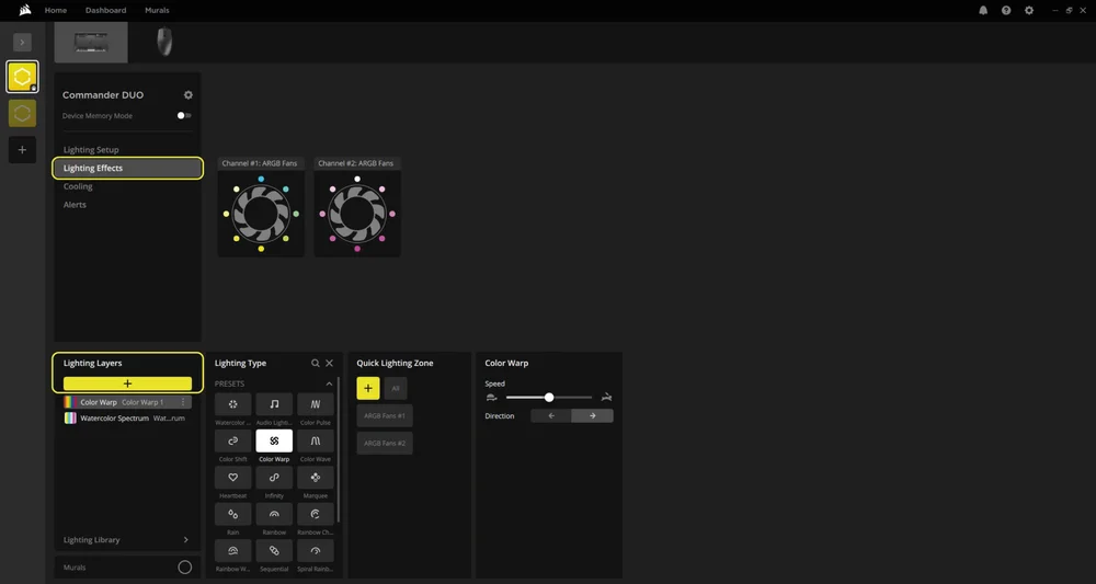
4. LIGHTING EFFECTS
Choose which lighting effect will be displayed when the iCUE software is running:
- Select "Lighting Effects" in the main menu on the left.
- Select the desired lighting effect.
- Click the "+" icon in the "Lighting Layers" panel to add additional lighting effects.
ARGB Mode
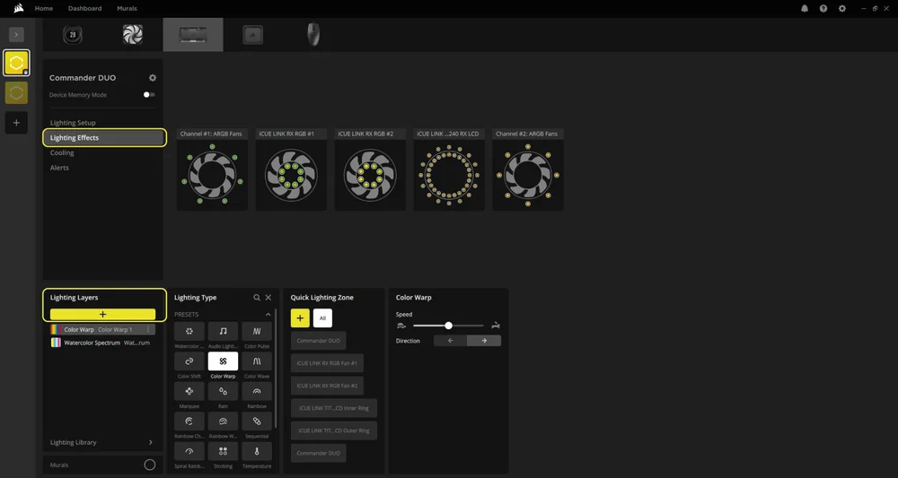
LINK Mode
Device Memory Mode
Choose which lighting effect will be displayed when iCUE software is not running - usually during computer the startup phase:
- Select "Lighting Effects" in the main menu on the left.
- Toggle the Device Memory Mode by clicking on the button.
- Select the desired lighting effect by clicking on one of the available options in the "Lighting Type" panel and click on the save icon.
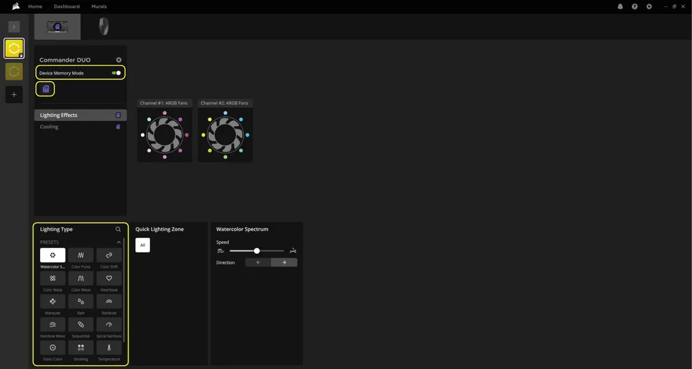
ARGB Mode
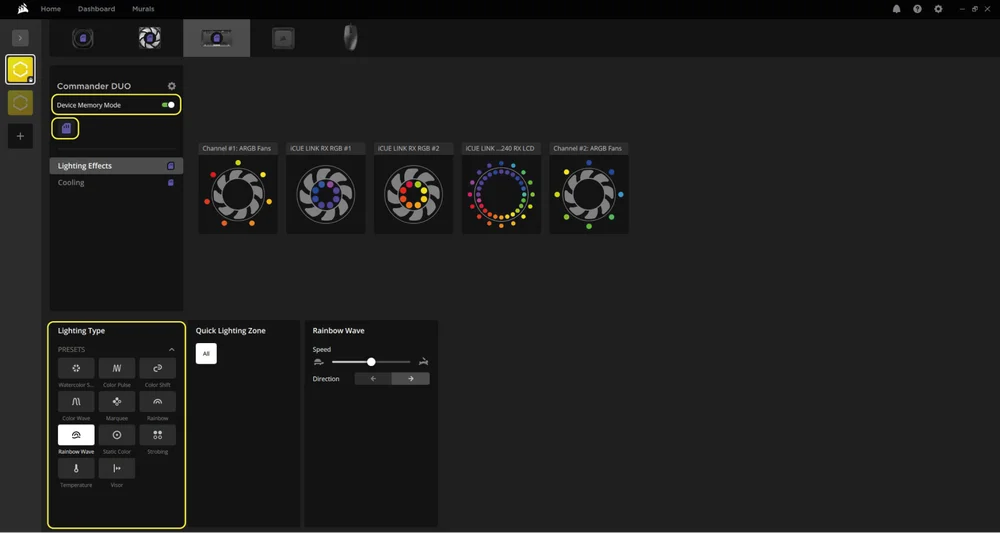
LINK Mode
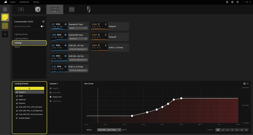
5. COOLING SETUP
Select your desired cooling presets for any fans connected to the COMMANDER DUO between Quiet, Balanced, Extreme, or create your own fan curve:
- Select "Cooling" in the main menu on the left
- Select the desired cooling preset for each device.
- Click the "+" icon under "Cooling Presets" to create a custom fan curve.
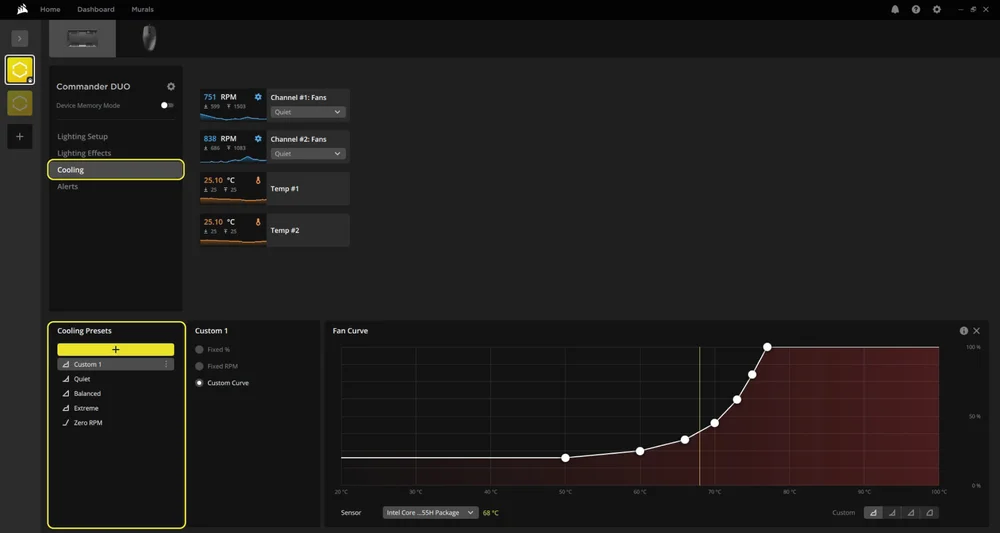
ARGB Mode
LINK Mode
Device Memory Mode
Choose how your fan(s) will perform when the iCUE software is not running - usually during computer the startup phase:
- Select "Cooling" in the main menu on the left.
- Toggle the Device Memory Mode by clicking on the button.
- Select one of the available presets in the “Cooling Presets” panel.
- Once the desired setting is selected, click on the save icon.
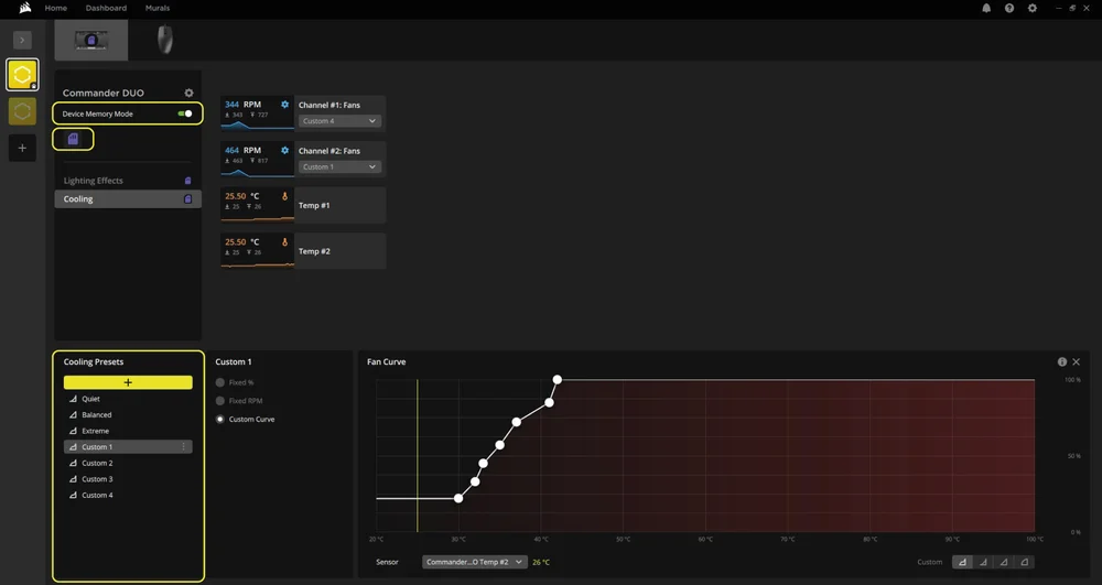
ARGB Mode
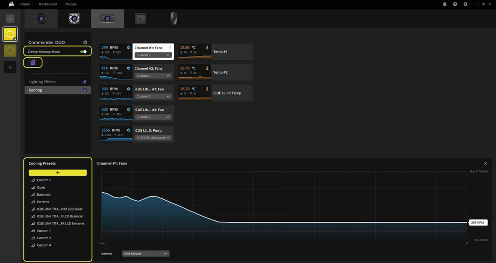
LINK Mode
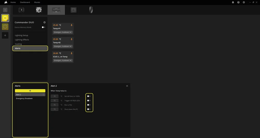
6. ALERTS
You can configure automatic actions based on temperature thresholds. The interface displays available temperature inputs (Temp #1 and Temp #2) detected by the connected sensors.
- Select "Alerts" in the main menu on the left.
- Click the "+" icon in the “Alerts" panel on the bottom to create custom actions.
- Use the toggle switches to enable one or more actions for that temperature condition.
- Assign a specific temperature input (Temp #1 or #2) to this alert using the dropdown menu next to each sensor block.
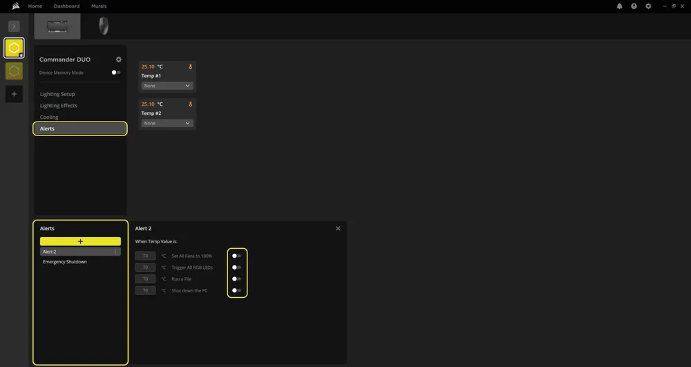
ARGB Mode
LINK Mode
FREQUENTLY ASKED QUESTIONS
Can I use SATA power when the iCUE LINK System Hub is attached to power more devices?
No. The controller should operate in either ARGB Fan Controller Mode or LINK Mode (via the iCUE LINK System Hub), but not both. Connecting the USB cable, SATA power and iCUE LINK System Hub simultaneously may cause communication conflicts and unpredictable behavior.
What happens if I exceed the LED limit on an ARGB header?
Each 3-pin ARGB header supports up to 50 LEDs. Exceeding this limit may lead to reduced brightness, incorrect lighting patterns, or software instability. Always check your LED count before connecting.
Can I daisy-chain multiple ARGB devices on a single header?
Yes, but keep in mind the total LED count must not exceed 50 per header. Many ARGB fans and strips allow daisy-chaining, but you must verify the LED count of each device.
Are temperature sensors necessary for operation?
No. The temperature sensors are optional. However, they are recommended if you want to monitor specific zones in your system.
What are smart features in CORSAIR iCUE software?
Smart features in CORSAIR iCUE allow you to monitor your system, customize lighting and cooling, create automated profiles, and control compatible devices intelligently based on real-time conditions.
POWER RATING
COMMANDER DUO
Output Rating: 12V 1.5A (per Fan port), 5V 1.8A (per ARGB port), 12V 7A (iCUE LINK)
WARRANTY

The CORSAIR COMMANDER DUO has a 3-year warranty.
LEGAL
© 2025 CORSAIR MEMORY, Inc. All rights reserved. CORSAIR and the sails logo are registered trademarks of CORSAIR in the United States and/or other countries. All other trademarks are the property of their respective owners. Product may vary slightly from those pictured.
RELATED CONTENT