-
A BILLENTYŰZET MEGISMERÉSE
-
MŰSZAKI ADATOK
-
OPCIONÁLIS – KIEGÉSZÍTŐ MODULOK
-
CORSAIR MGX HYPERDRIVE MÁGNESES BILLENTYŰKAPCSOLÓK
-
AXON HIPERFELDOLGOZÁSI TECHNOLÓGIA
-
A BILLENTYŰZET BEÁLLÍTÁSA
-
SONY PLAYSTATION CSATLAKOZTATÁSA
-
VEZETÉK NÉLKÜLI CSATLAKOZÁS (Csak telepített vezeték nélküli modullal érhető el)
-
TÖLTÉS & AKKUMULÁTOR ÉLETTARTAMA
-
ÜZEMMÓDOK
-
HARDVER ÁTTEKINTÉS
-
SZOFTVER ÁTTEKINTÉS
-
iCUE KEZDŐLAP ÉS ESZKÖZKÉPERNYŐ
-
GYÁRI BEÁLLÍTÁSOK VISSZAÁLLÍTÁSA
-
AZ AKKUMULÁTOR KIVÉTELÉVEL KAPCSOLATOS TUDNIVALÓK
-
SZERZŐI JOG / JOGI INFORMÁCIÓK
KÉZIKÖNYV | GYORS KEZDETI ÚTMUTATÓ
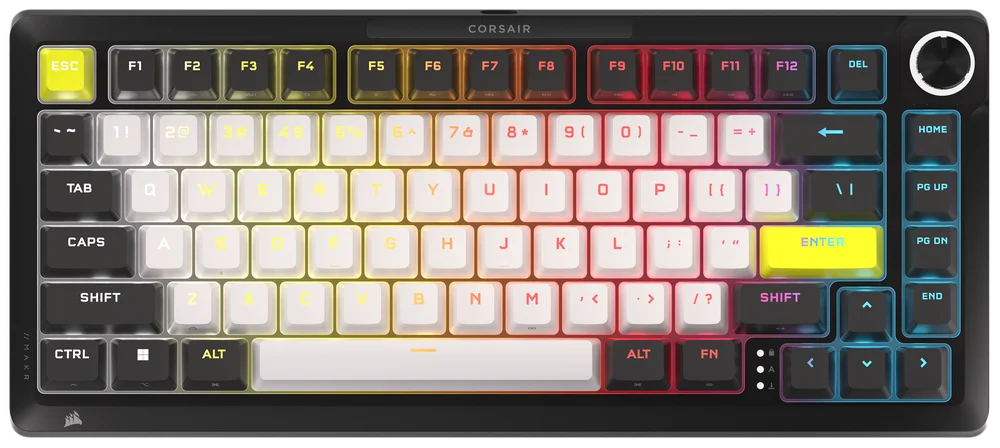
MAKR PRO 75
HALL EFFECT DIY BILLENTYŰZET
Az angol verzió itt érhető el - English
Ha bármilyen más problémája van, kérjük lépjen kapcsolatba ügyfélszolgálat
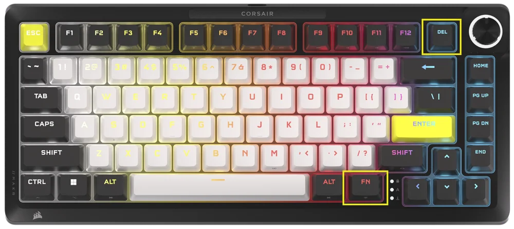
A BILLENTYŰZET MEGISMERÉSE
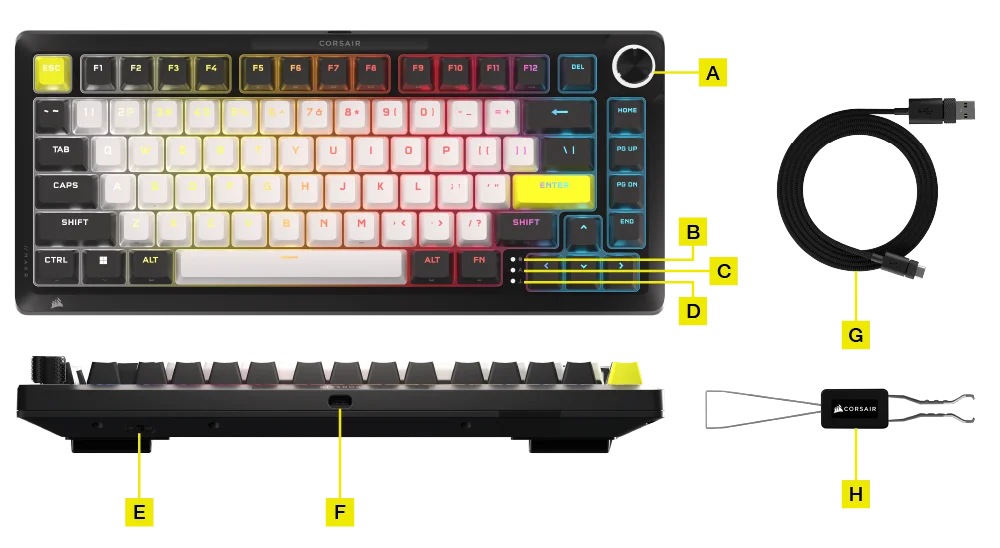
- TÖBBFUNKCIÓS TEKERŐGOMB
- WINDOWS LOCK JELZŐ
- CAPS LOCK JELZŐ
- SCROLL LOCK JELZŐ
- WIN/MAC VÁLTÓ
- USB C TÍPUSÚ PORT
- TYPE-C USB TYPE-A KÁBELHEZ
- 2 AZ 1-BEN BILLENTYŰKAPCSOLÓ/BILLENTYŰSAPKA
OPCIONÁLIS - KIEGÉSZÍTŐ MODULOK:
- Vezeték nélküli modul
- LCD modul
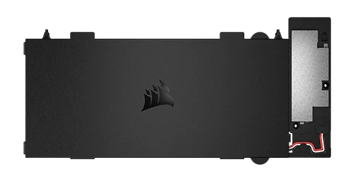
A VEZETÉK NÉLKÜLI MODUL TELEPÍTÉSE
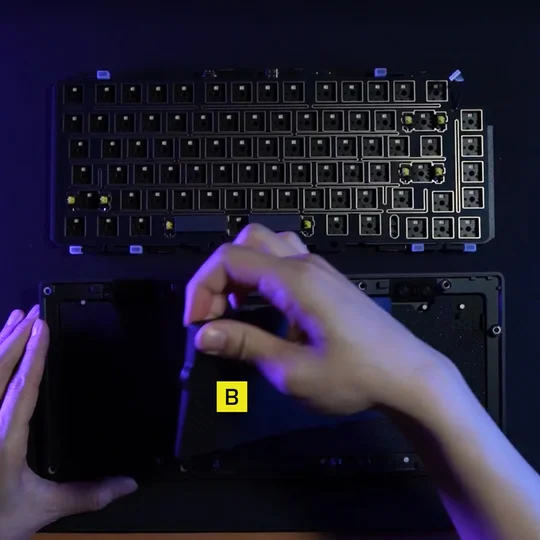
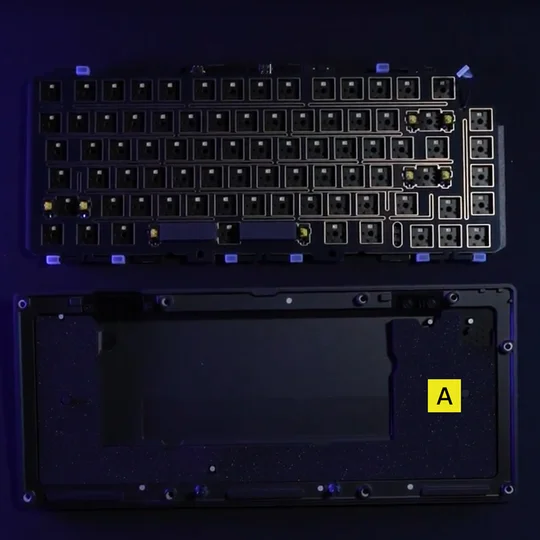
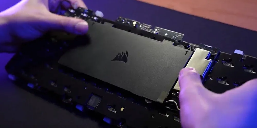
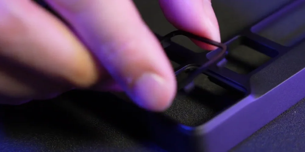
1. Nyitott billentyűzet mellett távolítsa el az összes belső alkatrészt, kivéve az alsó rétegeket, ahol az akkumulátor számára kialakított kivágás található.
MEGJEGYZÉS: A vezetékes modellben található egy gumibetét (B), kérjük, távolítsa el a (B) részt, csak az akkumulátor kivágásához tartozó betétet (A) hagyja meg.
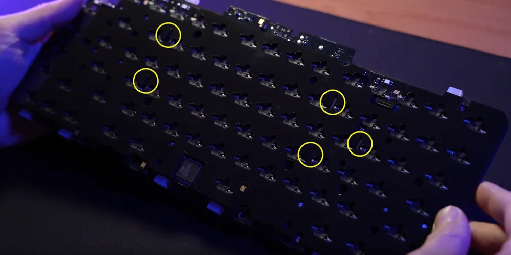
2. Telepítse a vezeték nélküli modult úgy, hogy a műanyag tüskéket a foglalat habszivacsának hátulján található megfelelő nyílásokhoz illeszti. Vannak vizuális jelzők, amelyek segítenek ebben a folyamatban. Miután a műanyag tüskék egy vonalban vannak, gyakoroljon némi nyomást a modul négy sarkára, amíg a helyükre nem pattannak.
(1)
(2)
(3)
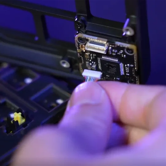
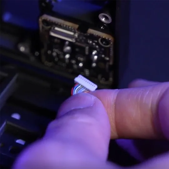
MEGJEGYZÉS:
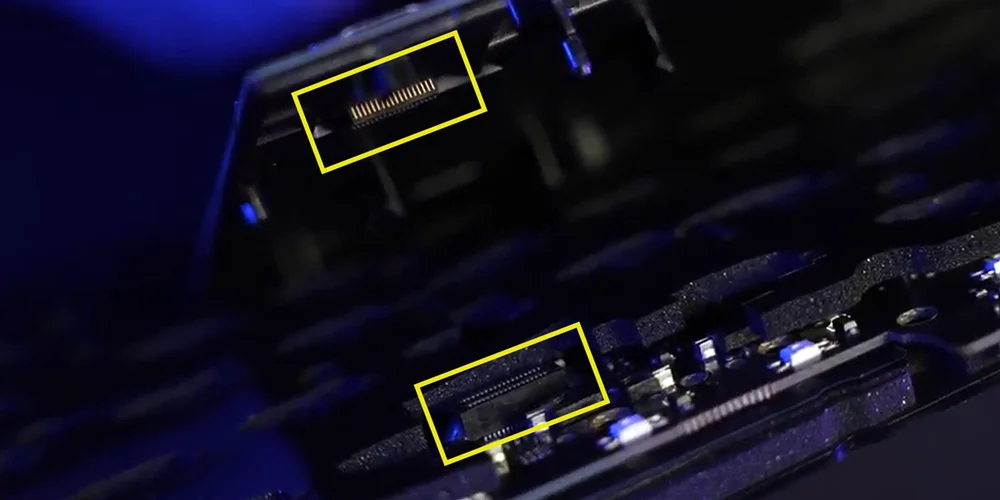
A vezeték nélküli modul a NYÁK-hoz való csatlakoztatásakor győződjön meg arról, hogy ez a két csatlakozó teljesen a helyén van. (1. Kép)
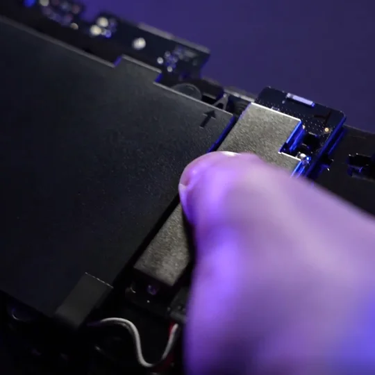
Ezt úgy teheti meg, hogy finoman megnyomja a vezeték nélküli modul ezüst részét (2. kép), amíg kattanást nem hall.
Ha nem hall kattanást, hagyja abba a nyomást, és térjen vissza a 2. lépéshez, hogy megbizonyosodjon arról, hogy az összes műanyag tüske a helyén van, mielőtt újra megnyomná az ezüst részt.
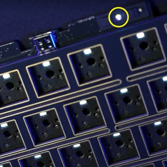
Amikor a vezeték nélküli modul sikeresen telepítve lett, egy fehér LED világít, amikor a billentyűzet be van kapcsolva. (3. Kép)
(1)
(2)
(3)
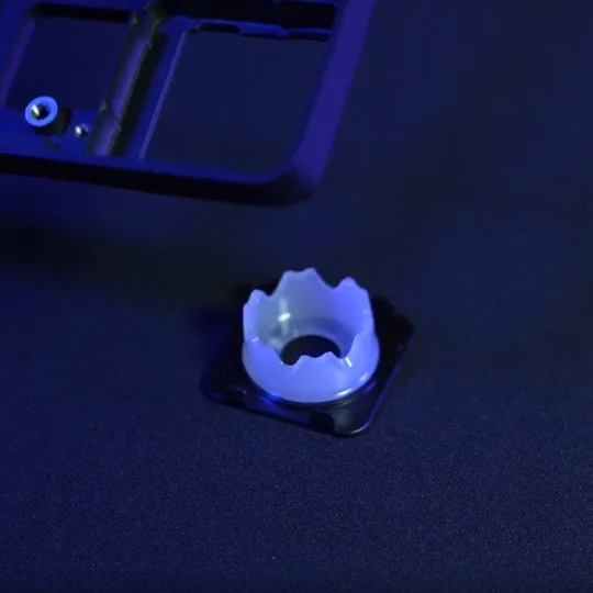
3. Cserélje ki a műanyag homlokrészt a „CORSAIR” feliratúra  a vezeték nélküli modulhoz mellékelt új műanyag gombvédőkkel.
A helyes telepítési sorrend balról jobbra a következő kell legyen:
a. Be-/kikapcsolás
b. CORSAIR védjegy
c. SLIPSTREAM 2.4GHz gomb
d. Bluetooth® gomb
VEZETÉK NÉLKÜLI KAPCSOLAT ENGEDÉLYEZÉSE
-
Ha a Vezeték nélküli modul telepítve van, csúsztassa a bekapcsológombot ON állásba a billentyűzet bekapcsolásához.
-
Nyomja meg a Vezeték nélküli gombot a SLIPSTREAM vezeték nélküli 2,4 GHz-es módba váltáshoz.
Bekapcsológomb ON állásba csúsztatva / Vezeték nélküli gomb lenyomva
Tartsa lenyomva a SLIPSTREAM párosítás megkezdéséhez.
-
Nyomja meg a BT gombot a Bluetooth üzemmódra való váltáshoz.
Tartsa lenyomva a Bluetooth párosítás megkezdéséhez.
Bekapcsológomb ON állásba csúsztatva / BT gomb lenyomva
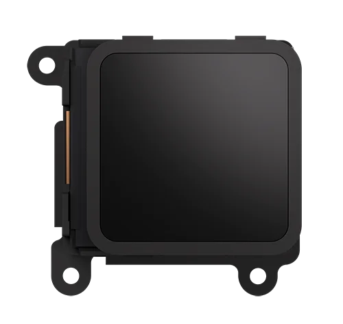
AZ LCD MODUL TELEPÍTÉSE
1. Vegye ki a tekerőgombos modult.
- Fordítsa a készletet fejjel lefelé, és távolítsa el a ház csavarjait.
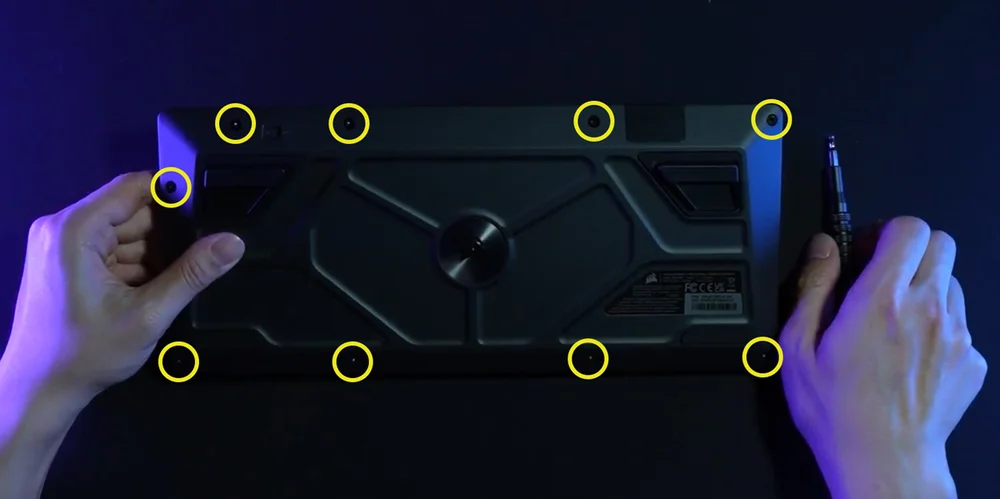
- Miután eltávolította a csavarokat, óvatosan fordítsa vissza a házat, miközben egyben tartja, hogy az alkatrészek ne eshessenek szét.
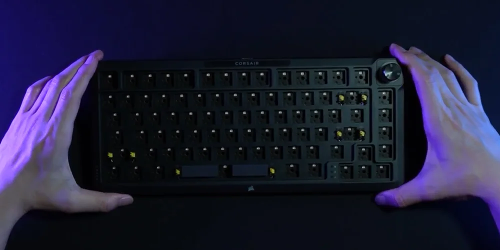
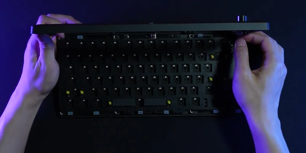
- Húzza le a modult.
- Óvatosan emelje fel a felső házrészt. Húzza ki a szalagkábelt a házból.
(1)
(2)
(3)
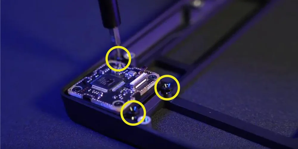
- Távolítsa el a tekerőgombos modult rögzítő három csavart.
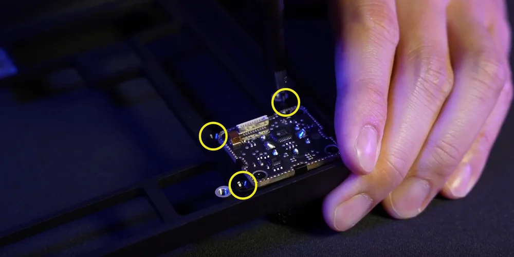
- Teljesen távolítsa el a tekerőgombos modult, és tárolja biztonságos helyen.
(1)
(2)
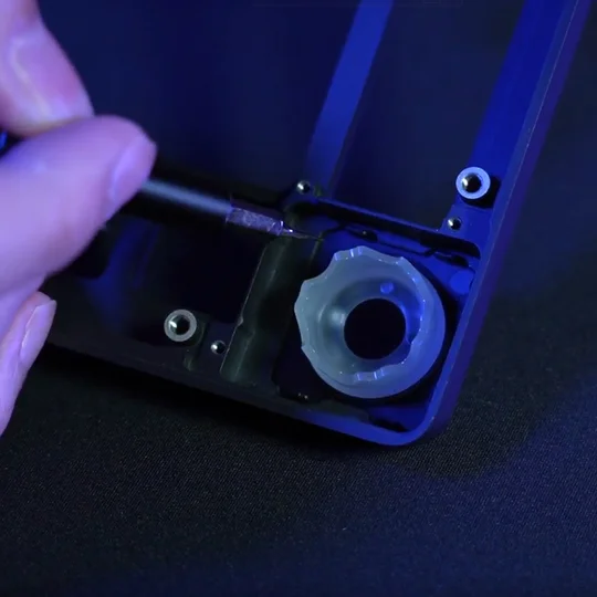
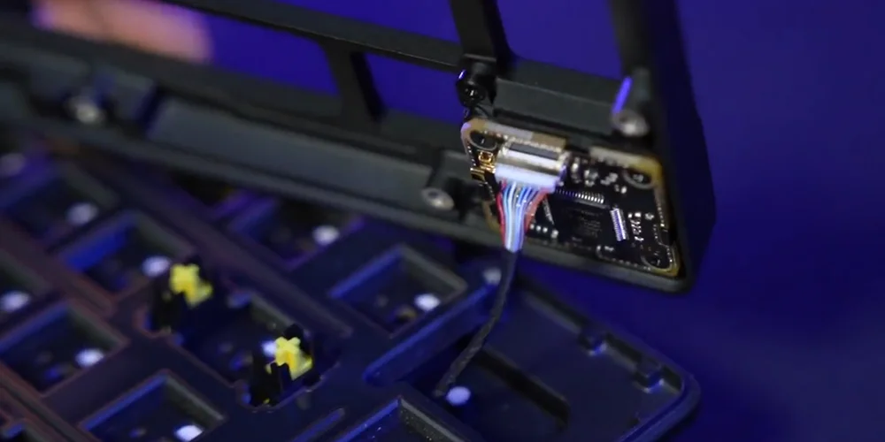
2. LCD modul telepítése
- Szerelje fel a gyűrűt a felfelé néző házra. (Hátra néző helyzetben nem működik.)
- Fordítsa hátra az LCD-t, és rögzítse három csavarral.
- Csatlakoztassa újra a szalagkábelt a felső házához.
MŰSZAKI ADATOK
| JELLEMZŐ | LEÍRÁS |
| Kialakítás | 75% |
| Felső fedél | Teljesen alumínium |
| Alsó rész | Teljesen alumínium |
|
Színváltozat |
Eclipse |
|
Hangelnyelő hab (Fentről lefelé) |
8 réteg
|
| Kapcsolólemez | FR4 (szilikon tömítésekkel) |
| Háttérvilágítás | Egyedileg LED-ekkel megvilágított és gombonként programozható |
| LED szín | RGB |
| Billentyűsapkák | PBT double shot |
| Billentyűkapcsolók |
CORSAIR MGX Hyperdrive mágneses, előre kent billentyűkapcsolók, 30–55 g működtető erő, 0,1–4,0 mm* működtetési távolság (0,1 mm-es lépésekben), 4,1 mm teljes út, 150 millió billentyűleütésig garantálva * Az optimális precizitás érdekében az ajánlott tartomány 0,3–3,6 mm. A működtetés ajánlott tartományon kívüli beállítása nagyobb érzékenységet eredményezhet, és befolyásolhatja a konzisztenciát |
| Csatlakoztathatóság | USB Type-A |
| Mátrix | Teljes billentyűleolvasás (NKRO) 100%-os anti-ghosting funkcióval |
| USB jelentési sebesség | Akár 8000 Hz-es hiperlekérdezés |
| Beépített profilok | Alapértelmezett: 1, legfeljebb 5 profil lehet |
| Médiavezérlés | FN gyorsbillentyűk/Tekerőgomb |
| FlashTap (SOCD) |
FN + jobb Shift iCUE felhasználói felület CORSAIR WEB HUB |
| Fényerő-szabályozás | FN gyorsbillentyűk/Tekerőgomb |
| Állítható magasság | Igen |
| Plug&play működés | Igen |
| Konzol kompatibilitás | Xbox One, Xbox Series X|S, PlayStation 4, 5 |
| Kábel | 1,8 m/6 láb, USB Type-C – Type-A, levehető, fekete, gumiból készült, gubancmentes gumiborítás |
| Méretek | 332(H) x 145(Sz) x 50(M) mm |
| Súly | 1,3 kg |
| Garancia | Két év – az ország helyi szabályozása érvényes |
OPCIONÁLIS – KIEGÉSZÍTŐ MODULOK
VEZETÉK NÉLKÜLI MODUL
| Méretek | 188,8(H) x 90,7(Sz) x 11,9(M) mm |
| Súly | 111,9 g |
| Garancia | Két év – az ország helyi szabályozása érvényes |
| Akkumulátor specifikációi | Típus: Beépített lítium-ion polimer, újratölthető |
|
Akkumulátor élettartama:
|
|
| Töltés: USB-n keresztül tölthető, körülbelül 5 óra alatt, az akkumulátor lemerülésétől és a használattól függően | |
| Konfiguráció: 1S1P | |
| Mennyiség: 1 | |
| Cellák: 1 | |
| Modell#: 2670155 | |
| Kapacitás: 4170mAh | |
| Méret: 159 (H) x 70,3 (SZ) x 3,0 (M) mm | |
| Méretek (kábellel): 199 (H) x 70,3 (SZ) x 3,0 (M) mm | |
| Súly 71 g | |
| Lítiumtartalom: 1,251 g | |
| HAZMAT UN #: UN3481 | |
| HAZMAT leírás: PI967 – Berendezésben található |
LCD MODUL
| Méret | 1,3 hüvelyk |
| Felbontás | 240x240 felbontás |
| Méretek | 33,77 (H) x 36,26 (SZ) x 15,8 (M) mm |
| Súly | 13,5 g |
| Képfeltöltési specifikációk |
|
| Garancia | Két év – az ország helyi szabályozása érvényes |
CORSAIR MGX HYPERDRIVE MÁGNESES BILLENTYŰKAPCSOLÓK
A CORSAIR MGX Hyperdrive mágneses billentyűkapcsolók szupersima, halk és holtjáték nélküli gépelési érzetet biztosítanak, és 0,1 mm és 4,0 mm* között programozható a billentyűleütés-érzékelésük. Így teljes mértékben a felhasználó irányíthatja az egyes billentyűleütések érzékenységét, hogy a játék és a gépelés élménye teljes mértékben igazodjon az egyéni igényekhez.
* Az optimális precizitás érdekében az ajánlott tartomány 0,3–3,6 mm. A működtetés ajánlott tartományon kívüli beállítása nagyobb érzékenységet eredményezhet, és befolyásolhatja a konzisztenciát.

AXON HIPERFELDOLGOZÁSI TECHNOLÓGIA
A CORSAIR AXON erőteljes és érzékeny gyors billentyűzetélményt nyújt a következőkkel:
- Rendkívül gyors billentyűleütés-érzékelés és feldolgozás.
- Akár 8000 Hz-es hiperlekérdezés (az iCUE és CORSAIR WEB HUB eszközbeállításaiban állítható be).
- Akár 20 rétegű, a billentyűzeten tárolt fényeffektek (profilonként programozható a iCUE-ban)

A BILLENTYŰZET BEÁLLÍTÁSA
| Windows® PC | Apple Mac® |
Microsoft Xbox One* Microsoft Xbox Series X | S* |
Sony PlayStation 4** Sony PlayStation 5** |
**Lásd a Sony PlayStation csatlakoztatása című részt.
SONY PLAYSTATION CSATLAKOZTATÁSA
A billentyűzet rendelkezik egy speciális móddal is, amely támogatja a Sony PlayStation 4 és 5 konzolokat, és amely gyorsbillentyűvel aktiválható.
| GYORSBILLENTYŰ | FUNKCIÓ | JELZÉS |
| FN+ |
Átváltás PlayStation módba | |
| FN+ |
Visszaváltás normál módba |
MEGJEGYZÉS: Az elérhető funkciók korlátozottak lehetnek a játékkonzol-támogatástól és az alkalmazástól függően.
VEZETÉK NÉLKÜLI CSATLAKOZÁS (Csak telepített vezeték nélküli modullal érhető el)
Amikor az USB-kábelt csatlakoztatja, a készülék automatikusan USB-módba vált.
Amikor az USB-kábelt kihúzza, a készülék a legutóbb használt vezeték nélküli módra vált.
| FUNKCIÓ NEVE | GOMB | FUNKCIÓ | JELZŐ | JELZÉS/ÁLLAPOT |
| USB-kábel | NEM ALKALMAZHATÓ | Automatikusan USB módba vált, amikor a kábelt csatlakoztatja. | Vezeték nélküli gomb |
Folyamatosan világító sárga |
| SLIPSTREAM vezeték nélküli | Vezeték nélküli gomb |
Nyomja meg a vezeték nélküli gombot a SLIPSTREAM vezeték nélküli 2,4 GHz-es módra való váltáshoz | Vezeték nélküli gomb |
Folyamatosan világító fehér: Csatlakoztatva Pulzáló fehér: Nincs csatlakoztatva |
| Tartsa lenyomva a vezeték nélküli gombot a párosítás megkezdéséhez* | Párosítás közben 120 másodpercig gyorsan fehéren villog | |||
| Bluetooth 1 | Bluetooth gomb |
|
Bluetooth gomb |
Folyamatosan világító kék: Csatlakoztatva. Pulzáló kék: Nincs csatlakoztatva
Párosítás közben 120 másodpercig gyorsan kéken villog |
| Bluetooth 2 | Bluetooth gomb |
|||
| Bluetooth 3 | Bluetooth gomb |
*SLIPSTREAM vezeték nélküli párosítás: A dongle-t az iCUE-n keresztül is párosíthatja a billentyűzettel.
Lépések: A párosító (Pair) gomb a dongle oldalán található, sárga körrel jelölve.
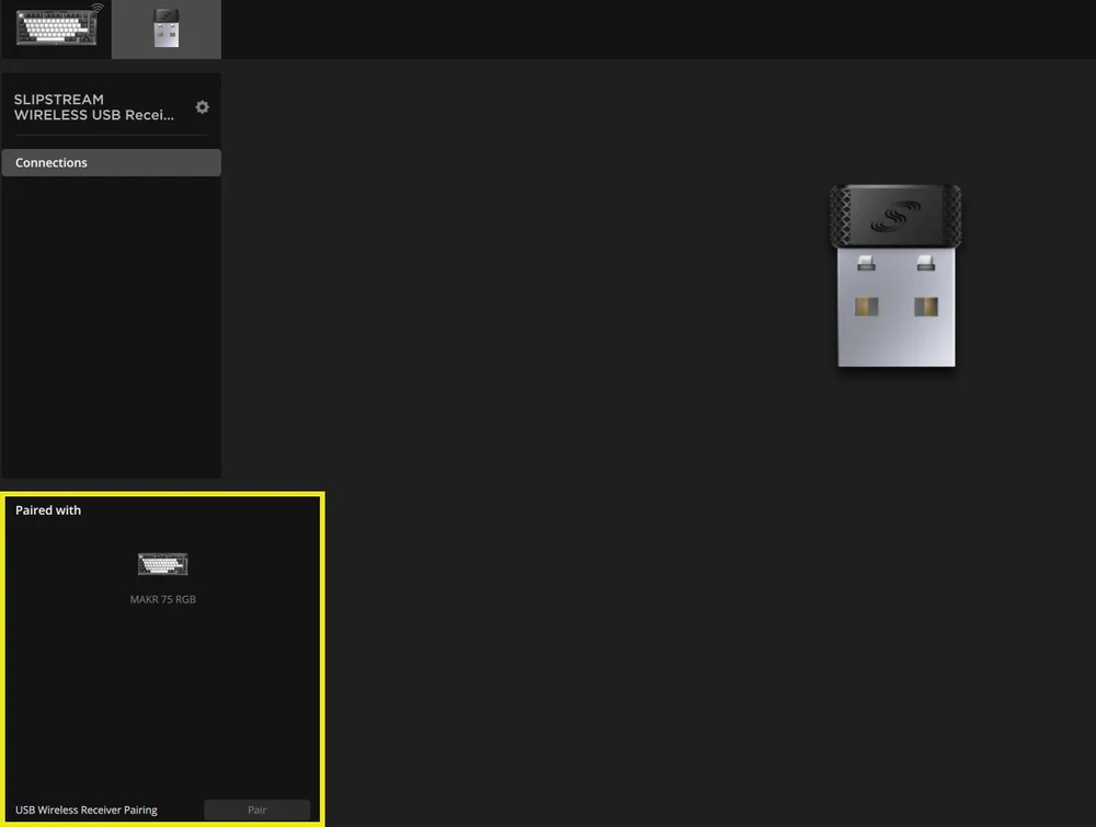
*A SLIPSTREAM vezeték nélküli adapterrel való párosítás befejezéséhez indítsa el az adapter párosítását az iCUE eszközbeállításaiban.
TÖLTÉS & AKKUMULÁTOR ÉLETTARTAMA
| FUNKCIÓ NEVE | GOMB | FUNKCIÓ | JELZÉS |
| Akkumulátor ellenőrzése | FN + Esc |
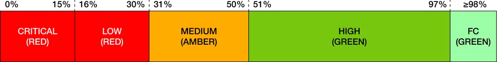
Az FN + Esc együttes lenyomásával az Esc billentyűn 3 másodpercig látható lesz az akkumulátor szintjét jelző fényhatás. |
Kritikus: Pirosan pulzál (folyamatban lévő esemény) Alacsony: Pirosan villog Közepes: Borostyánsárgán villog Magas: Zölden villog Teljesen feltöltve: Folyamatosan zöld *Ha USB-kábellel tölti az eszközt, a jelzőfény zölden villog, amíg a készülék teljesen fel nem töltődik. A jelzőfény folyamatos zöld világításra vált, ha a készülék teljesen fel van töltve. |
ÜZEMMÓDOK
A billentyűzet három üzemmóddal rendelkezik:
- Hardver (HW) mód – Amikor az iCUE nem fut, vagy a billentyűzet olyan eszközhöz csatlakozik, amely nem támogatja az iCUE-t, a billentyűzet hardver módban működik, amely a beépített tárhelyre mentett profilokat és beállításokat használja.
- Szoftver (SW) mód – Amikor az iCUE PC-n vagy Mac-en fut, a billentyűzet szoftver módban működik, és az iCUE vezérli.
- Töltse le az iCUE-t acorsair.com/downloads weboldalról, és telepítse Windows PC-re vagy Apple Mac-re, hogy az összes CORSAIR iCUE-kompatibilis termékét egyetlen felületen csatlakoztathassa, így teljes kontrollt kapva a világítástól a fejlett makrókig..

- Töltse le az iCUE-t acorsair.com/downloads weboldalról, és telepítse Windows PC-re vagy Apple Mac-re, hogy az összes CORSAIR iCUE-kompatibilis termékét egyetlen felületen csatlakoztathassa, így teljes kontrollt kapva a világítástól a fejlett makrókig..
- Webes mód – Amikor az iCUE nem fut, látogasson el a következő CORSAIR Web Hub linkre: https://corsair.com/web-hub. A billentyűzet web alapú módban működik, a beépített tárhelyre mentett profilokat és beállításokat használva.

| FUNKCIÓ | HARDVER MÓD | WEBES MÓD | SZOFTVER MÓD |
| Tárhely és profilok | 1 profiltól akár 5 profilig | 5 profil | Korlátlan |
| Új profilok létrehozása | Létrehozás az iCUE-ban | Létrehozás a CORSAIR WEB HUB-on | Létrehozás az iCUE-ban |
| Fényeffektek létrehozása | Létrehozás az iCUE-ban | Létrehozás a CORSAIR WEB HUB-on | Létrehozás az iCUE-ban |
| Kulcs-hozzárendelések létrehozása | Létrehozás az iCUE-ban | Létrehozás a CORSAIR WEB HUB-on | Létrehozás az iCUE-ban |
| Maximális megvilágítási rétegek | 20 | 5 |
Korlátlan (vezetékes mód) 20 (vezeték nélküli mód) |
HARDVER ÁTTEKINTÉS
FN PARANCSOK - VILÁGÍTÁSJELZŐ
Az FN billentyű lenyomásakor az összes világítás pillanatnyilag kikapcsol, kivéve azokat a billentyűket, amelyekhez másodlagos funkciók és makrók vannak rendelve. Ezeknek a billentyűknek a háttérvilágítása be lesz kapcsolva.
- Az alapértelmezett szín fehér lesz.
- A felhasználók testre szabhatják a színjelzést az iCUE-ben.
Az aktuálisan használt profil színjelzése elsőbbséget élvez az FN gyorsbillentyű világításával szemben.
HARDVERES MŰKÖDTETÉS BEÁLLÍTÁSA (A. TÁBLÁZAT)
Kérjük, győződjön meg arról, hogy mind az iCUE, mind a CORSAIR WEB HUB ki van kapcsolva, mielőtt a hardveres működtetés beállítását elvégezné.
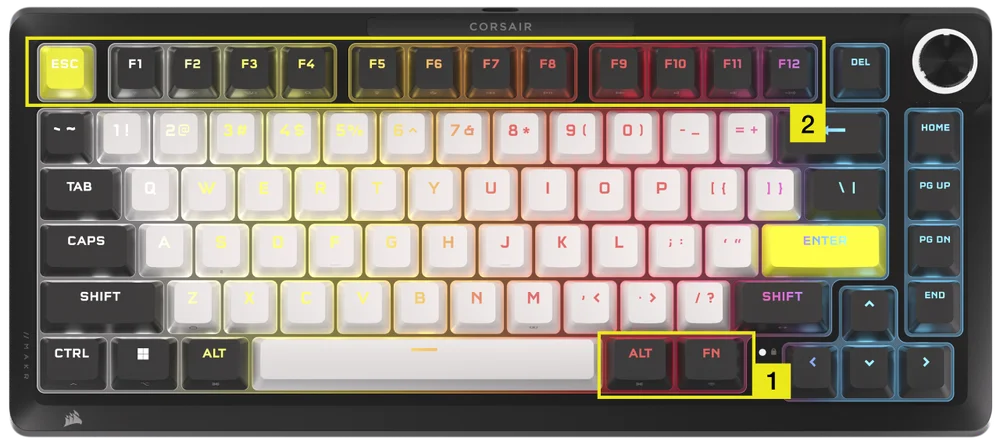
- Tartsa lenyomva az FN + jobb Alt billentyűkombinációt 2 másodpercig, amíg a billentyűzet világítása ki nem kapcsol, kivéve az ESC, F1-F12, 4-0, -_ és =+ billentyűket.
- Nyomja meg az ESC és az F1–F12 közül valamelyik világító billentyűt, hogy beállítsa az összes billentyűt az adott működtetési távolságra.
- Az összes analóg billentyű (kivéve az ESC, F1-F12, 4-0, -_ és =+ billentyűket, de beleértve a kiválasztottakat is) lélegző effekttel világít (kiválasztott szín).
- Nyomja meg ugyanazt az érzékenységi gombot az aktuális Hardver mód beállításra való visszatéréshez.
| Billentyű | ESC | F1 | F2 | F3 | F4 | F5 | F6 |
| Működtetési távolság (mm) | 0,8 | 1,0 | 1,2 | 1,4 | 1,6 | 1,8 | 2,0 (alapértelmezett) |
| Szín | Fehér | Narancs | Borostyánsárga | Sárga | Zöld | Ciánkék | Türkiz |
| Billentyű | F7 | F8 | F9 | F10 | F11 | F12 |
| Működtetési távolság (mm) | 2,2 | 2,4 | 2,6 | 2,8 | 3,0 | 3,2 |
| Szín | Kék | Indigókék | Lila | Ibolya | Magenta | Piros |
- Nyomja meg az FN + jobb Alt billentyűkombinációt a kilépéshez és az új beállítások kipróbálásához.
| Játék (gyorsabb reakcióidő) | Általános használat (kiegyensúlyozott) | Gépelés (javított precizitás) |
| 1,0 mm | 2,0 mm (alapértelmezett) | 3,0 mm |
Szoftveres módban, az iCUE használatával még erőteljesebb vezérlési lehetőségekhez férhet hozzá: az aktiválási beállítások 0,1 mm-es lépésekben finomhangolhatók a teljes 0,1 mm–4,0 mm* tartományon belül. Ezek profilonként elmenthetők, illetve másodlagos működtetéshez műveletek rendelhetők, ami lehetővé teszi a gyors egymás utáni (rapid fire) kombinációkat vagy a fejlett sétálás–futás mozgásvezérlést.
*Az optimális precizitás érdekében az ajánlott tartomány 0,3 mm–3,6 mm. A működtetés ajánlott tartományon kívüli beállítása nagyobb érzékenységet eredményezhet, és befolyásolhatja a konzisztenciát.
HARDVERES GYORSKIOLDÓ MŰKÖDTETÉS BEÁLLÍTÁSA (B. TÁBLÁZAT)
Kérjük, győződjön meg arról, hogy mind az iCUE, mind a CORSAIR WEB HUB ki van kapcsolva, mielőtt a hardveres működtetés beállítását elvégezné.
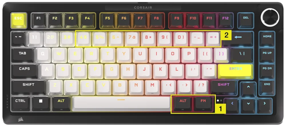
- Tartsa lenyomva az FN + jobb Alt billentyűkombinációt 2 másodpercig, amíg a billentyűzet világítása ki nem kapcsol, kivéve az ESC, F1-F12, 4-0, -_ és =+ billentyűket.
- Nyomja meg a 4–0, -_ és =+ billentyű közül a világító billentyűk egyikét a gyorskioldó működtetési pont beállításainak az összes billentyűre történő alkalmazásához.
- Nyomja meg ugyanazt az érzékenységi gombot az aktuális Hardver mód beállításra való visszatéréshez.
| Billentyű | 4 | 5 | 6 | 7 | 8 | 9 | 0 | -_ | =+ |
| Működtetési távolság (mm) | 0,4 | 0,5 | 0,6 |
0,7 |
0,8 | 0,9 | 1,0 (Defalt) | 1,1 | 1,2 |
| Szín | Borostyánsárga | Sárga | Zöld | Ciánkék | Türkiz | Kék | Lila | Magenta | Piros |
- Nyomja meg az FN + jobb Alt billentyűkombinációt a kilépéshez és az új beállítások kipróbálásához.
HARDVER KALIBRÁLÁSA
Speciális esetekben, amikor a működtetési pontok már nem működnek megfelelően, használható ez az egyedi hardveres kalibrációs eszköz.
Kérjük, győződjön meg arról, hogy mind az iCUE, mind a Corsair Web Hub ki van kapcsolva, mielőtt a hardveres működtetés beállítását elvégezné.
-
Tartsa lenyomva az FN + Delete billentyűkombinációt 2 másodpercig a kalibrációs módba való belépéshez
-
Minden billentyű folyamatosan fehér színnel világít, az FN billentyű folyamatosan zölden világít.
-
Tartsa lenyomva a kalibrálni kívánt billentyűket
a. Az FN billentyű és a lenyomva tartott billentyű folyamatos piros színnel világít kalibrálás közben
b. Az FN billentyű és a lenyomva tartott billentyű folyamatosan kék színnel világít ha a kalibrálás befejeződött
-
Engedje fel a kalibrálni kívánt billentyűt
a. Az FN billentyű és a lenyomva tartott billentyű folyamatos zöld színnel világít, ha a kalibrálás befejeződött
- Tartsa lenyomva az FN gombot 2 másodpercig a kalibrációs módból való kilépéshez és az eszköz alaphelyzetbe állításához
TEKERŐGOMB FUNKCIÓ
A tekerőgomb funkciói között 2 másodperc nyomva tartással válthat.
A tekerőgomb gyűrű az aktuális tárcsázási módnak megfelelő színt mutatja. Az aktuális tekerőgomb funkció nem változik ki- és bekapcsoláskor.
| MÓD | LED SZÍN | LED JELZÉS | TEKERÉS | LENYOMÁS |
| Hangerő | Fehér | Folyamatos |
|
Némítás/Némítás feloldása |
| Médiavezérlés | Kék | Folyamatos |
|
Lejátszás/szünet |
| Világítás | Ciánkék | A LED-ek világítása a fényerőtől függően (%) |
|
Bekapcsolás (100%)/Kikapcsolás (0%) |
| Makrófelvétel | Piros |
Üresjárati állapot: pirosan pulzál Felvételi állapot: pirosan villog Felvétel befejezése: Gyorsan villogó piros Törlési állapot: gyorsan villogó piros |
NEM ALKALMAZHATÓ | Makrórögzítés indítása |
| Zeneszám precíz tekerése | Zöld | Folyamatos |
Windows:
Mac OS Apple Music:
Mac OS Spotify:
|
NEM ALKALMAZHATÓ |
| Alkalmazásváltás | Lime | Folyamatos |
|
|
| Függőleges görgetés | Narancs | Folyamatos |
|
Ctrl + END |
| Vízszintes görgetés | Sárga | Folyamatos |
|
Ctrl + END |
| Zoomolás | Lila | Folyamatos |
|
Visszaállítás az alapértelmezett zoomolási műveletre |
| iCUE egyéni műveletek | Felhasználó által definiált | Folyamatos |
|
1. Művelet |
STANDARD GYORSGOMBOK
Az alábbi funkciók mindegyike feltételezi az FN billentyű lenyomva tartását, és a művelet annak megnyomásával aktiválódik, hacsak másképp nem jelezzük.
| FŐ | FUNKCIÓ |
KÉPERNYŐJELZŐ (Ha LCD van telepítve) |
MEGJEGYZÉSEK |
| FN + ESC | Akkumulátor ellenőrzése | Nem | Vezeték nélküli modul nélkül semmit sem csinál. |
| FN + F1 | A képernyő fényerejének csökkentése | Igen | |
| FN + F2 | A képernyő fényerejének növelése | Igen | |
| FN + F3 | Windows Feladatnézetének be- és kikapcsolása | Nem | macOS: Mission Control |
| FN + F4 | A Fájlkezelő elindítása | Nem | macOS: Spotlight keresés |
| FN + F5 | A billentyűzet LED fényerejének csökkentése 10%-os léptékben | Igen | macOS: Diktálás/Siri |
| FN + F6 |
A billentyűzet LED fényerejének növelése 10%-os léptékben |
Igen | macOS: Ne zavarj |
| FN + F7 | Előző médiaszám | Igen | |
| FN + F8 | Médiaszám lejátszása/szüneteltetése | Igen | |
| FN + F9 | Következő médiaszám | Igen | |
| FN + F10 | Némítás/némítás feloldása | Igen | |
| FN + F11 | Hangerő csökkentése 2%-os léptékben | Igen | |
| FN + F12 | Hangerő növelése 2%-os léptékben | Igen | |
| FN + S | Scroll Lock be- és kikapcsolása | Igen | macOS: Nincs funkció |
| FN + Z | Profilok váltogatása | Igen | Automatikusan megjeleníti a profil színét 5 mp-ig folyamatosan, hacsak más nem írja felül |
| FN + C | Beépített fényeffektek váltogatása | Igen | Tartsa lenyomva 2 másodpercig a beépített effektus visszaállításához |
| FN + V | Fényeffektek iránybeállításainak váltogatása | Igen | |
| FN + B | A fényeffekt sebességbeállításainak váltogatása | Igen | |
| FN + M | Makrófelvételi módba lépés | Igen | 2 Másodpercig kell tartani |
| FN + Win | Win Lock be- és kikapcsolása | Igen | |
| FN + jobb Shift | FlashTap be- és kikapcsolása | Nem | |
| FN + Balra nyíl | Mozgás balra a képernyő felhasználói felületén | Nem | Képernyő modul nélkül semmit sem csinál |
| FN + Jobbra nyíl | Mozgás jobbra a képernyőn felhasználói felületén | Nem | |
| FN + ENTER | Képernyőelem aktiválása | Nem |
MAKRÓFELVÉTEL
- Makrófelvételi módba lépés
- Tartsa lenyomva az FN + M billentyűket 2 másodpercig, vagy tartsa lenyomva a tekerőgombot makrófelvétel módban (a LED színe piros)
- Az M gomb jelzőfénye pirosan fog pulzálni.
- Ha van tekerőgomb vagy kijelző a billentyűzeten, akkor azoknak is jelezniük kell a makrófelvétel állapotát.
- A felvétel megkezdéséhez nyomjon meg bármilyen szabványos billentyűsorozatot
- Ez magában foglalja az olyan gyorsbillentyűket is, mint az FN + billentyűparancsok, amennyire lehetséges (a firmware/szoftver korlátai alapján), például az FN + S billentyűkombináció Scroll lockként van rögzítve.
- Csak a szabványos billentyűzetfunkciók rögzíthetők – speciális vagy beépített (onboard) funkciók, mint például az alábbiak, nem:
- Egérkurzor
- Profil
- Háttérvilágítási effektek
- Fényerő
- Média
- Hangerő
- Win lock
- Csak a szabványos billentyűzetfunkciók rögzíthetők – speciális vagy beépített (onboard) funkciók, mint például az alábbiak, nem:
- A késéseket is rögzíti
- Jelzés: Az M gomb (és a tekerőgomb, ha van) jelzőfénye pirosan villog
- Ez magában foglalja az olyan gyorsbillentyűket is, mint az FN + billentyűparancsok, amennyire lehetséges (a firmware/szoftver korlátai alapján), például az FN + S billentyűkombináció Scroll lockként van rögzítve.
- Nyomja meg az FN + M billentyűkombinációt 2 másodpercig vagy a tekerőgombot a felvétel leállításához és a makró mentésre vagy törlésre való előkészítéséhez.
- Ennek többszöri megnyomása nem vált ki további funkciót
- Jelzés: Az M gomb (és a tekerőgomb, ha van) jelzőfénye gyors ütemben pirosan villog
- Nyomjon meg egy tetszőleges billentyűt, majd FN + billentyűt
- Ha rögzítve lettek billentyűk: A billentyű vagy kombináció megnyomása menti a makrót
- Ha nem lettek rögzítve billentyűk: A billentyű vagy billentyűkombináció megnyomása törli a mentett makrót vagy funkciót
- Ha van egy firmware gyorsbillentyű, amely normális esetben ehhez a kombinációhoz van kötve, akkor az visszaáll
- Ezekre a billentyűkre vagy kombinációkra viszont nem lehet makrót rögzíteni:
- FN
- FN + M
- FN + ESC
- FN + Windows
- Jelzés: A makróhoz rendelt billentyűkombináció gyorsan pirosan villog
- MEGJEGYZÉS: A piros jelzőszín az alapértelmezett, a felhasználó módosíthatja.
FLASHTAP (SOCD)
A FlashTap egy forradalmi technológia, amely teljes irányítást ad a játékos kezébe a mozgásgombok – különösen a balra és jobbra mozgás – felett, optimalizálva az SOCD-viselkedést minden játékban és műfajban.
A FlashTap alapértelmezés szerint le van tiltva HW módban, valamint az iCUE és a CORSAIR WEB HUB esetében egyaránt.
Viselkedés HW módban
- Profilfüggetlen, engedélyezés parancsikonokkal: FN + Jobb SHIFT
- Az A + D billentyűket támogatja, de csak az utoljára lenyomott kap prioritást
- Jelzés: Az A és D billentyűk folyamatosan narancssárgán világítanak, ha a FlashTap funkció be van kapcsolva (ez felülírja a meglévő világítási beállításokat)
iCUE & Corsair Web Hub viselkedés (további részletek az iCUE & CORSAIR WEB HUB szakaszban)
- Támogatja a fejlett funkciókat, mint például a módválasztás és a billentyűkiosztás újraprogramozása
- Profillal konfigurálható
- Módválasztás részletei
|
Utolsó élvez prioritást (alapértelmezett, ha be van kapcsolva) |
Mindig az utoljára lenyomott irányt küldi ki, a másikat pedig figyelmen kívül hagyja |
| Semleges | Nincs kimenet, ha mindkét irány egyszerre aktiválódik |
| Első élvez prioritást | Mindig az elsőre lenyomott irányt küldi ki, a másikat pedig figyelmen kívül hagyja |
SZOFTVER ÁTTEKINTÉS
CORSAIR WEB HUB
A CORSAIR WEB HUB egy könnyen kezelhető, webalapú segédprogram a MAKR PRO 75 billentyűzet testreszabásához. Hatékony, könnyen használható, és nem igényel további szoftvertelepítést. Itt kipróbálható: https://corsair.com/web-hub

A CORSAIR WEB HUB első megnyitásakor látható a MAKR PRO 75 eszköz neve. A gombra kattintva megjelennek a következő, programozás megkezdéséhez szükséges lehetőségek jelennek meg:
- Fényeffektek
- Billentyű-hozzárendelések
- Többfunkciós billentyűk
- Billentyű működtetések
- Tekerőgomb
- FlashTap
- Kulcs kalibrálása
FÉNYEFFEKTEK
A Fényeffektek lapon a fényeffektek programozása végezhető el.
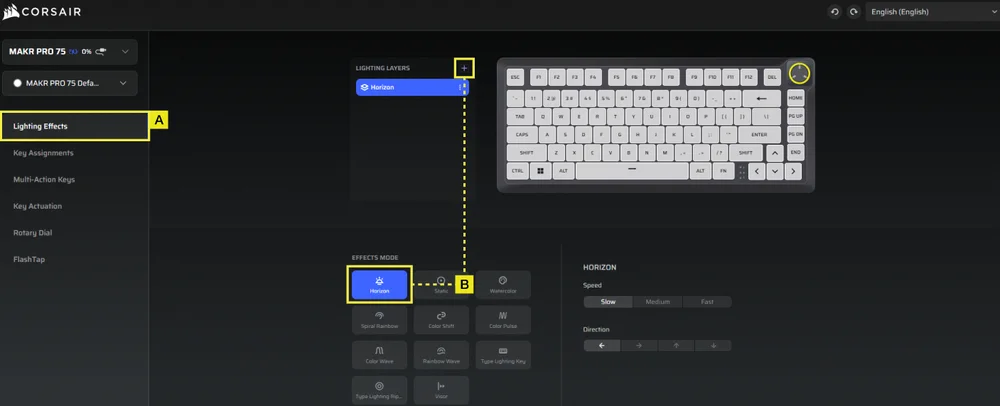
A. Válassza ki a Fényeffektek lapot.
B. Kattintson a + gombra a világítási rétegek tetszés szerinti beállításához.
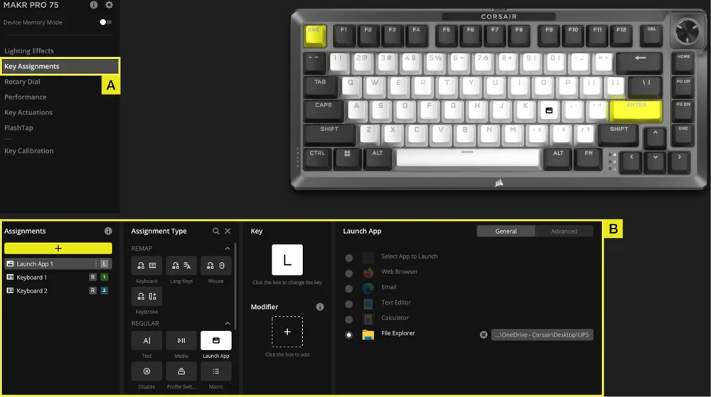
BILLENTYŰ-HOZZÁRENDELÉSEK
A Billentyű-hozzárendelések fül lehetővé teszi a billentyűk egyszerű átprogramozását vagy új funkciók hozzárendelését a billentyűkhöz.
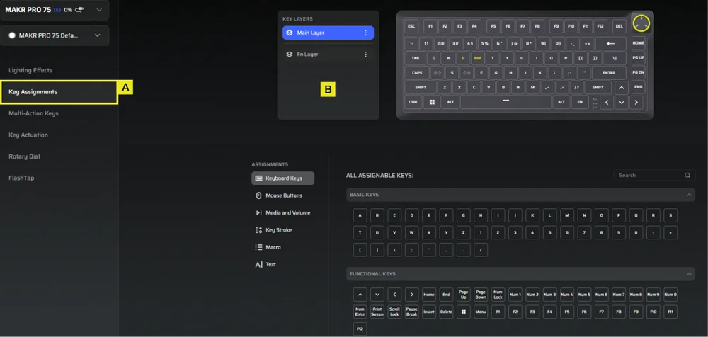
A. Válassza ki a Billentyű-hozzárendelések lapot.
B. Válassza ki a billentyűket a Fő rétegben vagy az FN rétegben, és rendelje őket a menüben felsorolt bármelyik funkcióhoz.
TÖBBFUNKCIÓS BILLENTYŰK
A Többfunkciós billentyűk fül lehetővé teszi a másodlagos működtetési pontok engedélyezését, ami speciális, 2 az 1-ben billentyűkombinációkat tesz lehetővé.
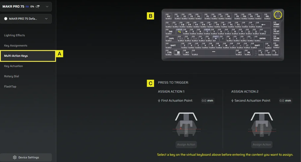
A. Válassza ki a Többfunkciós billentyűk lapot.
B. Válassza ki azokat a billentyűket, amelyekre ezt a beállítást alkalmazni kívánja.
C. Állítsa be a működtetési pontokat az 1. és a 2. művelethez. Ezután nyissa meg a mindkettőhöz a Művelet hozzárendelése panelt, hogy kiválaszthassa a kívánt funkciókat.
BILLENTYŰ MŰKÖDTETÉSEK
A Billentyű működtetések lapon állíthatja be a működtetési pontot. Az alapértelmezett beállítás 2,0 mm, és 0,1 mm–4,0*mm közötti tartományban állítható be. Itt található a Rapid Trigger beállítás is, amely lehetővé teszi a dinamikusan változó működtetési és visszaállítási pontok megváltoztatását.
*Az optimális precizitás érdekében az ajánlott tartomány 0,3 mm–3,6 mm. A működtetés ajánlott tartományon kívüli beállítása nagyobb érzékenységet eredményezhet, és befolyásolhatja a konzisztenciát.
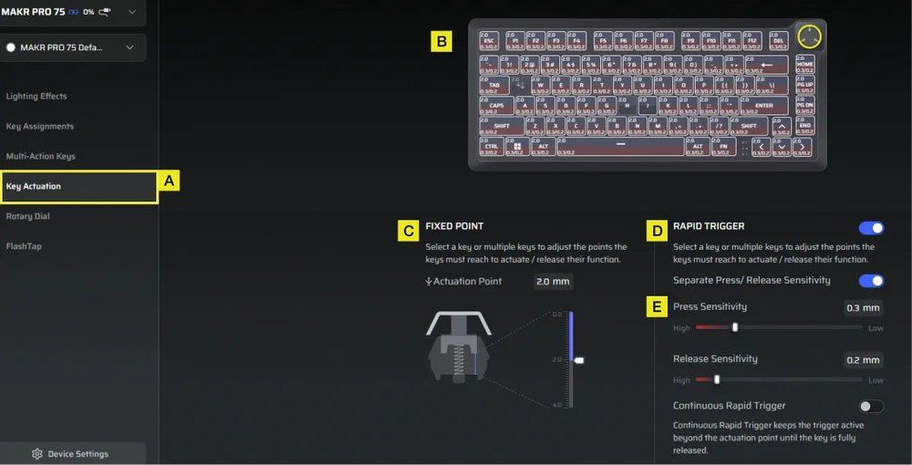
A. Válassza ki a Billentyű működtetések lapot.
B. Válassza ki a billentyűket a működtetési viselkedésük beállításához.
C. A Fix pont alatt állítsa be a működtetési pontot.
D. Kapcsolja be a Gyorskioldó (alapértelmezett a kikapcsolt állapot) funkciót a nyomási és elengedési pontok érzékenységének független beállításához.
E. A csúszkákkal finomhangolhatja a Nyomásérzékenység és az Elengedés érzékenységet, vagy engedélyezheti a Folyamatos gyorskioldást a gyorsabb ismételt bemenetekhez.
FORGÓTÁRCSA
A Tekerőgomb lapon kiválaszthatja, hogy melyik módot szeretné használni.
Az alapértelmezett beállítás szerint az összes mód be van kapcsolva.

A. Válassza a Tekerőgomb lapot.
B. Válassza ki a tekerőgomb módot.
FLASHTAP (SOCD)
A FlashTap (SOCD) lapon három különböző beállítás közül választhat, és rendelhet hozzá bizonyos billentyűpárokat a FlashTap támogatásához.
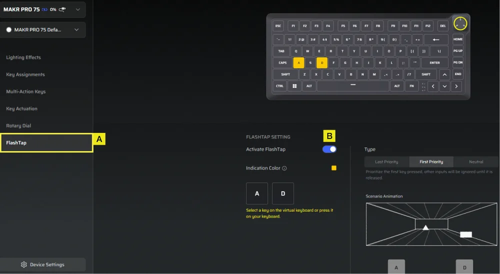
A. Válassza ki a FlashTap lapot.
B. Kapcsolja be a FlashTap funkciót (alapértelmezett a kikapcsolt állapot), majd válassza ki a kívánt beállítást, és rendelje hozzá a két billentyűt a kívánt módon.
KULCSKALIBRÁLÁS
A „Key Calibration” (Kulcsos kalibrálás) fülön kalibrálhatja a „Calibration Settings” (Kalibrálási beállítások) panelen felsorolt mágneses kapcsolókat.
(Lásd az oktatóvideót: https://youtu.be/pVrzB89FWBw)
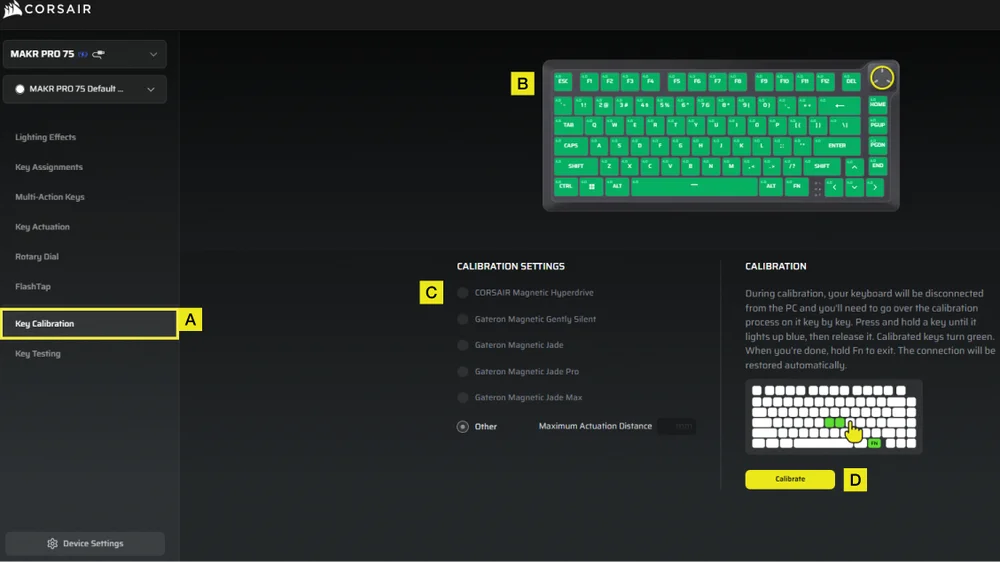
A. Válassza ki a „Billentyűk kalibrálása” fület.
B. Válassza ki a kalibrálni kívánt gombokat.
C. A „Kalibrálási beállítások” menüpontban a kapcsolótípusok kijelölésre várva megvilágulnak. Válassza ki az adott gombokra szerelt kapcsolótípust.
D. Kattintson a „Kalibrálás” gombra.
E. A billentyűzet ideiglenesen lekapcsolódik a számítógépről, és a rendszer a portál oldalára irányítja Önt. A folyamat során kövesse az alábbi lépéseket a kalibrálás befejezéséhez:
- Tartsa lenyomva egy gombot, amíg az a gomb és az FN gomb kigyullad egyszínű kék, majd engedje el a gombot.
- Az FN gomb és a Hold gomb bekapcsolja egyszínű zöld a kalibrálás befejezése után.
- Tartsa lenyomva az FN gombot 2 másodpercig a kalibrálási módból való kilépéshez és a készülék visszaállításához – ekkor megjelenik az indítási animáció.
- A kalibrálási folyamat befejezése után visszatér a kalibrálási oldalra.
ESZKÖZBEÁLLÍTÁSOK
Az Eszközbeállítások lapon módosíthatja a speciális beállításokat, beállíthatja a lekérdezési gyakoriságot és frissítheti a firmware-t.
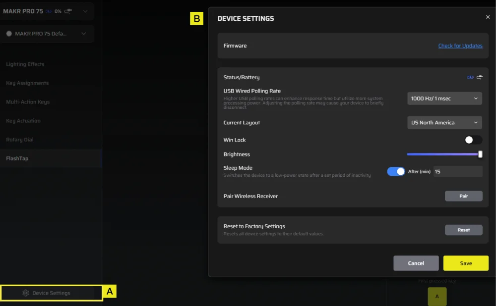
A. Kattintson az Eszközbeállítások fülre.
B. Módosítsa a speciális beállításokat (lekérdezési sebesség, fényerő...stb.).
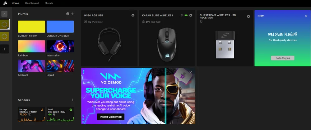
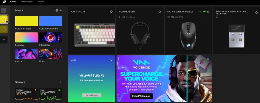
iCUE KEZDŐLAP ÉS ESZKÖZKÉPERNYŐ
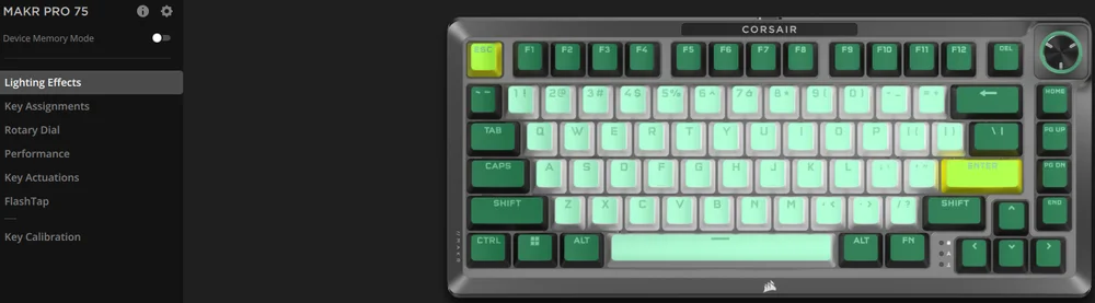
Az iCUE első megnyitásakor egy új eszközcsempe látható a MAKR PRO 75-höz. Az eszköz csempére kattintva a következő, programozás megkezdéséhez szükséges lehetőségek jelennek meg:
- Fényeffektek
- Billentyű-hozzárendelések
- Tekerőgomb
- Teljesítmény
- Billentyű működtetések
- FlashTap
- Kulcs kalibrálása
Ha frissítési értesítést lát az iCUE ablakban, kattintson rá a firmware legújabb verzióra való frissítéséhez.
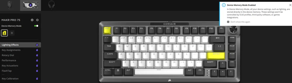
ESZKÖZ MEMÓRIA MÓD
A programozás megkezdése előtt vegye figyelembe, hogy minden iCUE rendszerprofilnak két beállításkészlete van: szoftver mód és eszközmemória mód.
Az Eszközmemória mód menü lehetővé teszi olyan funkciók hozzárendelését, amelyek a billentyűzet beépített memóriájába menthetők, és hardveres módban játszhatók le.
| FUNKCIÓ |
ESZKÖZ MEMÓRIA MÓD
|
SZOFTVER MÓD
|
| Tárhely és profilok | 1 MB legfeljebb 5 profilhoz | Korlátlan |
| Jellemzők |
|
|
| Mentés folyamata |
Manuális mentés
|
Automatikusan |
| Maximális megvilágítási rétegek | 20 |
Korlátlan |


FÉNYEFFEKTEK
A Fényeffektek lapon a fényeffektek programozása végezhető el.
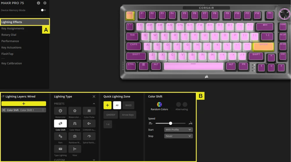
A. Válassza ki a Fényeffektek lapot.
B. A világítási rétegek alatt kattintson a [+] jelre a kívánt világítás beállításához
BILLENTYŰ-HOZZÁRENDELÉSEK
A Billentyű-hozzárendelések fül lehetővé teszi a billentyűk egyszerű átprogramozását vagy új funkciók hozzárendelését a billentyűkhöz.
A. Válassza ki a Billentyű-hozzárendelések lapot.
B. A Hozzárendelések alatt kattintson a [+] gombra a billentyűk átrendezéséhez vagy új funkciók hozzárendeléséhez.
FORGÓTÁRCSA
A Tekerőgomb lapon kiválaszthatja, hogy melyik módot szeretné használni.
Az alapértelmezett beállítás szerint az összes mód be van kapcsolva.
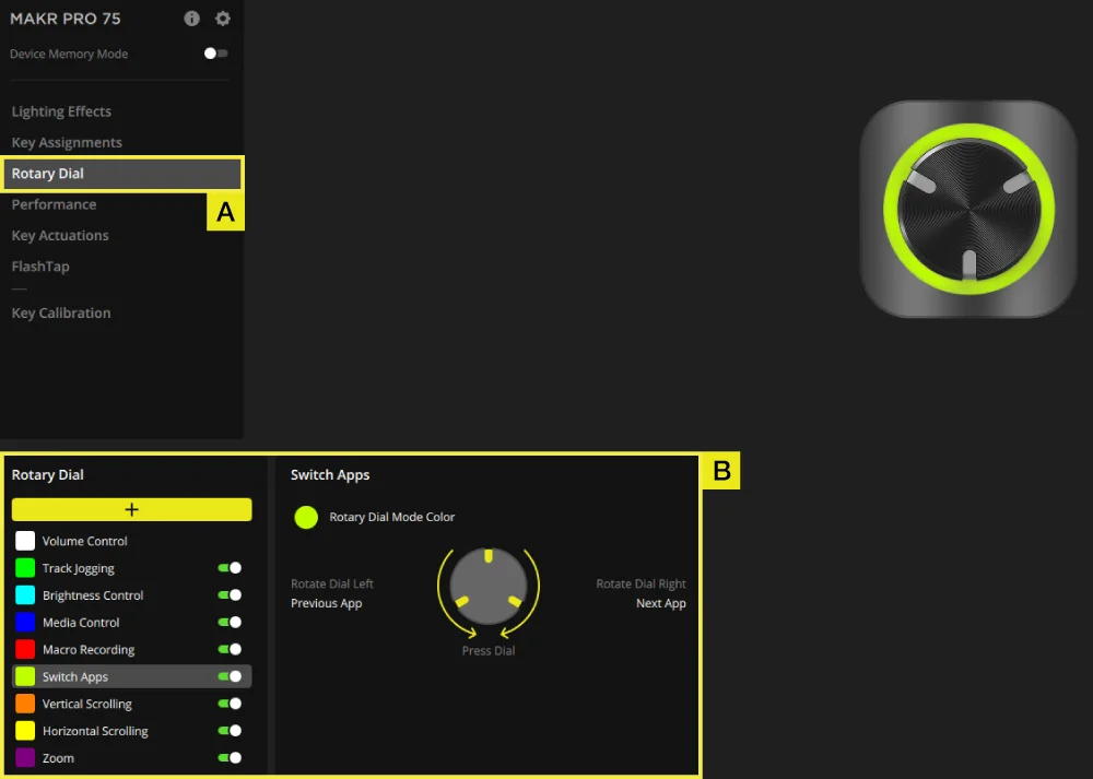
A. Válassza a Tekerőgomb lapot.
B. Kapcsolja be és ki a kívánt módokat.
TELJESÍTMÉNY
A Teljesítmény lapon engedélyezheti/letilthatja a gyorsbillentyűket, és testreszabhatja a jelzőszíneket.
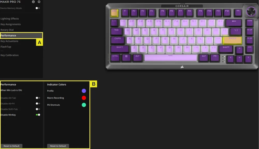
A. Válassza ki a Teljesítmény lapot.
B. Engedélyezze/tiltsa le a gyorsbillentyűket, vagy szabja testre a jelzőszíneket saját igényei szerint.
BILLENTYŰ MŰKÖDTETÉSEK
A Billentyű működtetések lapon állíthatja be a működtetési pontot. Az alapértelmezett beállítás 2,0 mm, és 0,1 mm–4,0*mm közötti tartományban állítható be. Itt található egy beállítás is a másodlagos működtetési pontok engedélyezéséhez, amelyek lehetővé teszik a fejlett 2-az-1-ben billentyűkombinációkat, valamint a gyorskioldás beállítás, amely dinamikusan változtatható működtetési és visszaállítási pontokat tesz lehetővé.
*Az optimális precizitás érdekében az ajánlott tartomány 0,3 mm–3,6 mm. A működtetés ajánlott tartományon kívüli beállítása nagyobb érzékenységet eredményezhet, és befolyásolhatja a konzisztenciát.
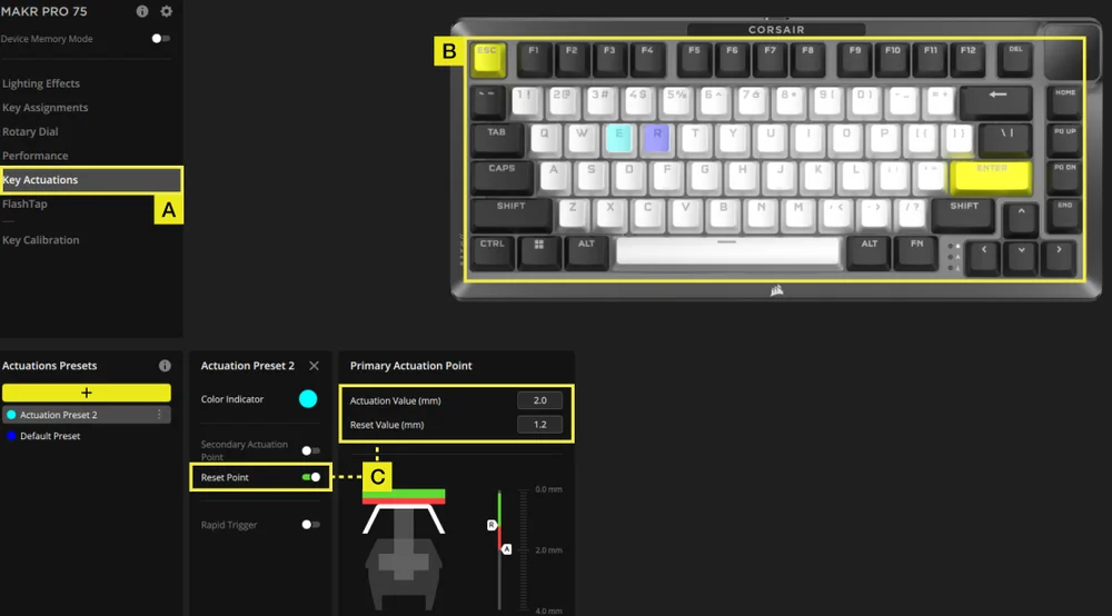
A. Válassza ki a Billentyű működtetések lapot.
B. Válassza ki azokat a billentyűket, amelyekre ezt a beállítást alkalmazni kívánja.
C. A Működtetési előbeállítások alatt kattintson a [+] gombra a működtetési érték 0,1 mm-es léptékben történő módosításához (alapértelmezett: 2 mm). Kapcsolja be a visszaállítási pontot (alapértelmezett: ki) a visszaállítási érték 0,1 mm-es léptékben történő beállításához (alapértelmezett: 1,9 mm).
KÉT MŰVELET BEÁLLÍTÁSA
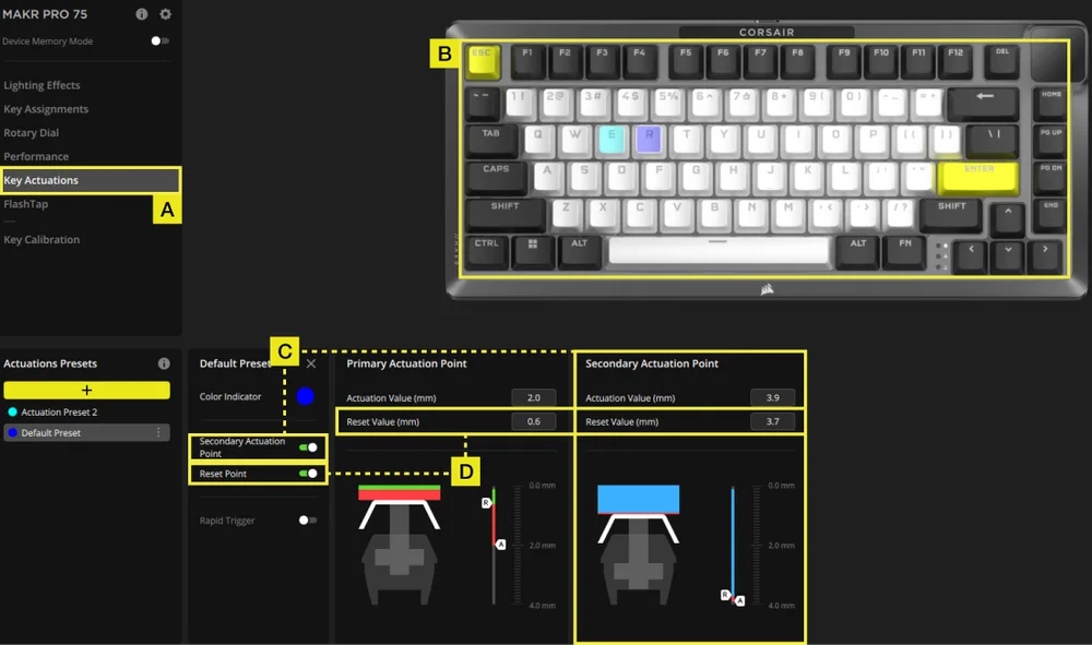
A. Válassza ki a Billentyű működtetések lapot.
B. Válassza ki azokat a billentyűket, amelyekre ezt a beállítást alkalmazni kívánja.
C. Kapcsolja be a Második működtetési pont kapcsolót (alapértelmezett: kikapcsolva) a másodlagos működtetési érték 0,1 mm-es léptékben történő beállításához (alapértelmezett: 3,5 mm).
D. Kapcsolja be a visszaállítási pontot (alapértelmezett: kikapcsolva) a visszaállítási érték 0,1 mm-es léptékben történő beállításához (elsődleges működtetés alapértelmezett: 1,9 mm; másodlagos működtetés alapértelmezett: 3,4 mm).
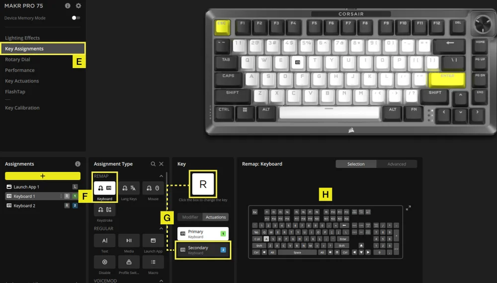
E. Válassza ki a Billentyű-hozzárendelések lapot.
F. A hozzárendelés típusa menüben válassza az újraprogramozás menüpontot.
G. Válassza ki azt a billentyűt, amelyhez két művelet van hozzárendelve, majd válassza ki a másodlagos műveletet a működtetés lapon.
H. Válassza ki azt a billentyűt, amely a hozzárendelni kívánt műveletet tartalmazza.
GYORSKIOLDÓ BEÁLLÍTÁSA
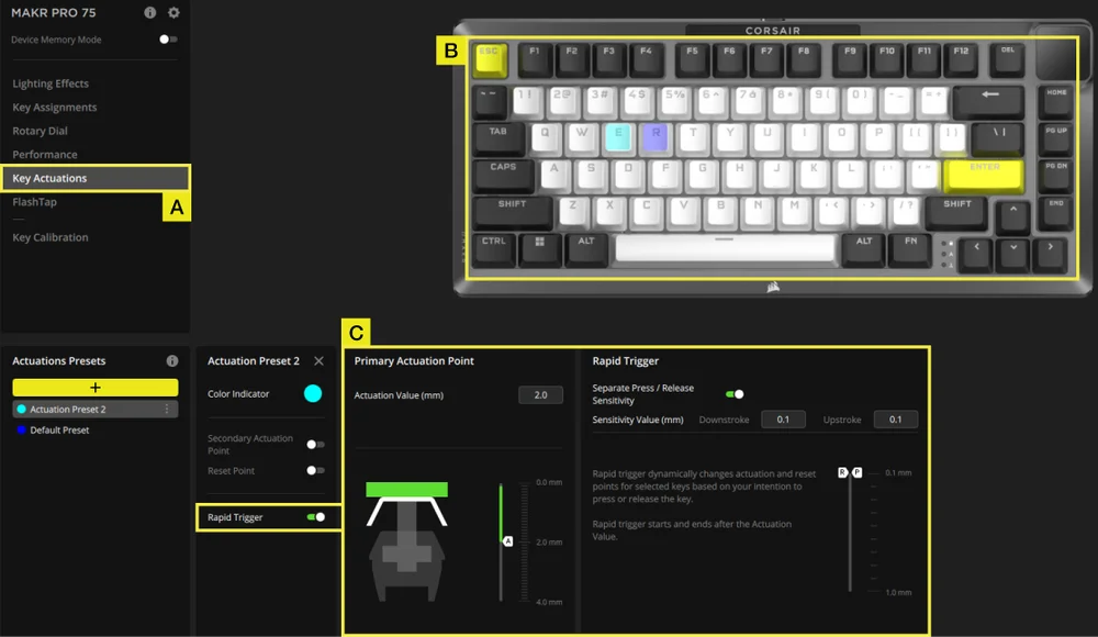
A. Válassza ki a Billentyű működtetések lapot.
B. Válassza ki azokat a billentyűket, amelyekre ezt a beállítást alkalmazni kívánja.
C. Gyorskioldó bekapcsolása (alapértelmezett: ki). Kapcsolja be az Eltérő nyomási/elengedési érzékenység funkciót (alapértelmezett: ki) a lenyomási és felengedési értékek beállításához (alapértelmezett: 0,1 mm)
Íme egy példa arra, hogyan konfigurálhatja az aktiválási pontokat, hogy a lehető legjobban kezeljen különböző helyzeteket. Javasoljuk a felhasználóknak, hogy próbálgassák és kísérletezzenek, hogy megtalálják a preferenciáiknak legmegfelelőbb beállítást.
| HASZNÁLAT | MŰKÖDTETÉSI ÉRTÉK | ELŐNY |
| Versenyjáték | 1,0 mm | Gyorsabb és érzékenyebb bevitelt tesz lehetővé. |
| Általános használat | 2,0 mm (alapértelmezett) | Jó középút a gyorsaság és a precizitás között. Ez az alapértelmezett beállítás. |
| Gépelés | 3,0 mm | Csökkenti a véletlen billentyűleütések valószínűségét. |
FLASHTAP (SOCD)
A FlashTap (SOCD) lapon három különböző beállítás közül választhat, és rendelhet hozzá bizonyos billentyűpárokat a FlashTap támogatásához.
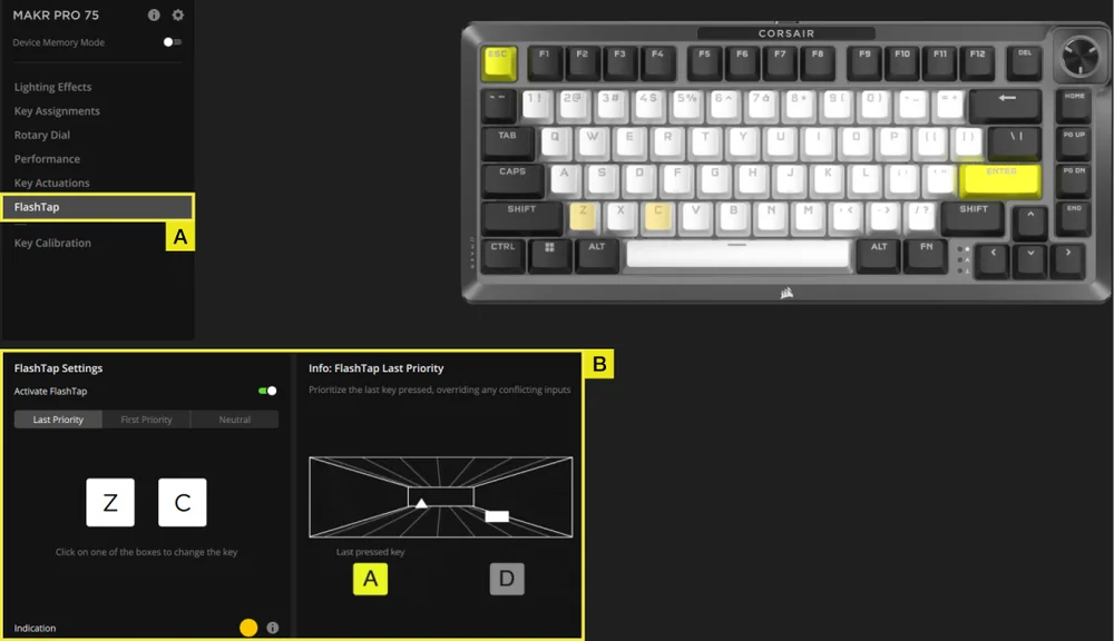
A. Válassza ki a FlashTap lapot.
B. Kapcsolja be a FlashTap funkciót (alapértelmezett a kikapcsolt állapot), majd válassza ki a kívánt beállítást, és rendelje hozzá a két billentyűt a kívánt módon.
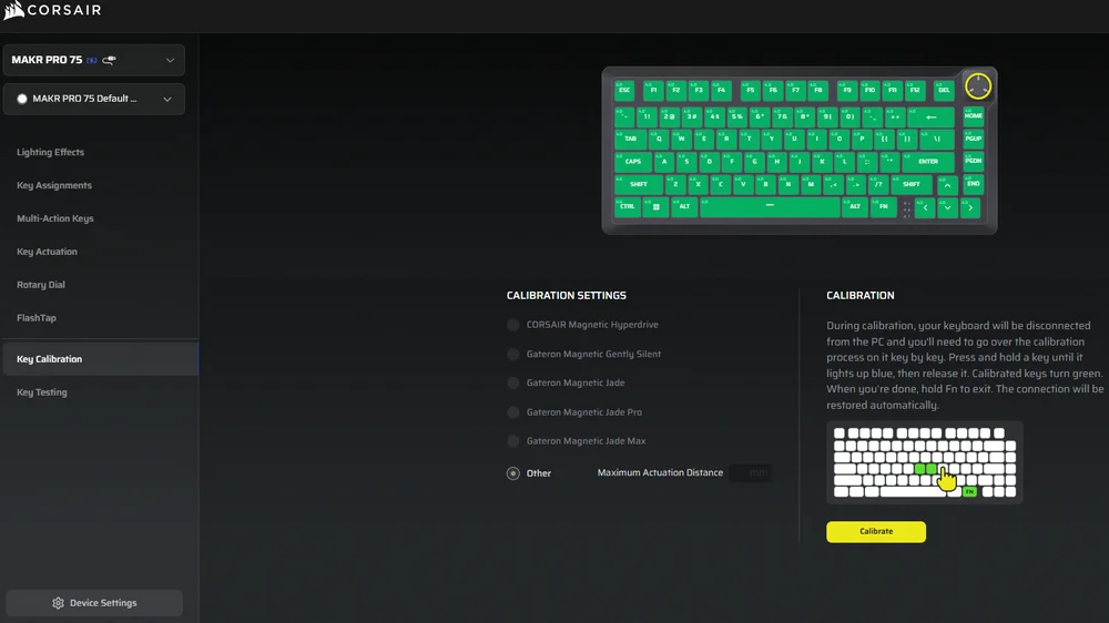
KULCSKALIBRÁLÁS
A „Key Calibration” (Kulcsos kalibrálás) fülön kalibrálhatja a „Calibration Settings” (Kalibrálási beállítások) panelen felsorolt mágneses kapcsolókat.
(Lásd az oktatóvideót: https://youtu.be/wbyFtZx3KEE)
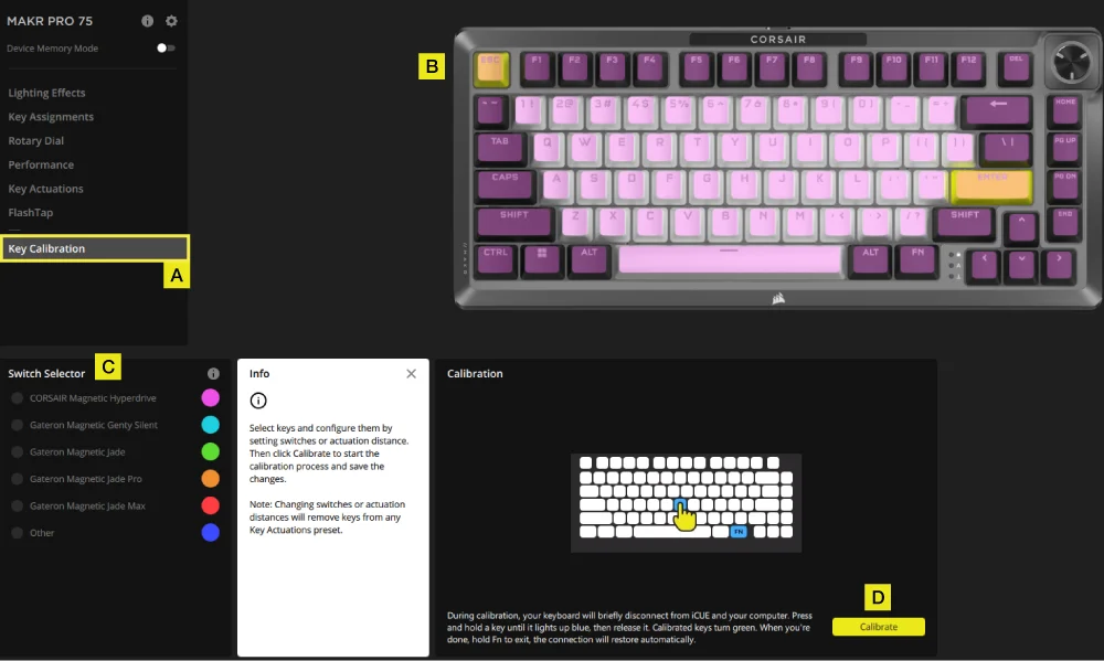
A. Válassza ki a „Billentyűk kalibrálása” fület.
B. Válassza ki a kalibrálni kívánt gombokat.
C. A kapcsolóválasztóban a kapcsolótípusok kijelölésre várva kiemelve jelennek meg. Válassza ki az adott gombokra szerelt kapcsolótípust.
D. Kattintson a „Kalibrálás” gombra.
E. A billentyűzet ideiglenesen lekapcsolódik a számítógépről, és a rendszer a portál oldalára irányítja Önt, ahol a MAKR PRO 75 készülék panelje nem lesz látható. Kövesse az alábbi lépéseket a kalibrálás befejezéséhez:
- Tartsa lenyomva egy gombot, amíg az a gomb és az FN gomb kigyullad egyszínű kék, majd engedje el a gombot.
- Az FN gomb és a Hold gomb bekapcsolja egyszínű zöld a kalibrálás befejezése után.
- Tartsa lenyomva az FN gombot 2 másodpercig a kalibrálási módból való kilépéshez és a készülék visszaállításához – ekkor megjelenik az indítási animáció.
- A kalibrálás befejezése után a MAKR PRO 75 újra megjelenik az eszközpanelen.
ESZKÖZBEÁLLÍTÁSOK
Az Eszközbeállítások lapon módosíthatja a speciális beállításokat, beállíthatja a lekérdezési gyakoriságot és frissítheti a firmware-t.
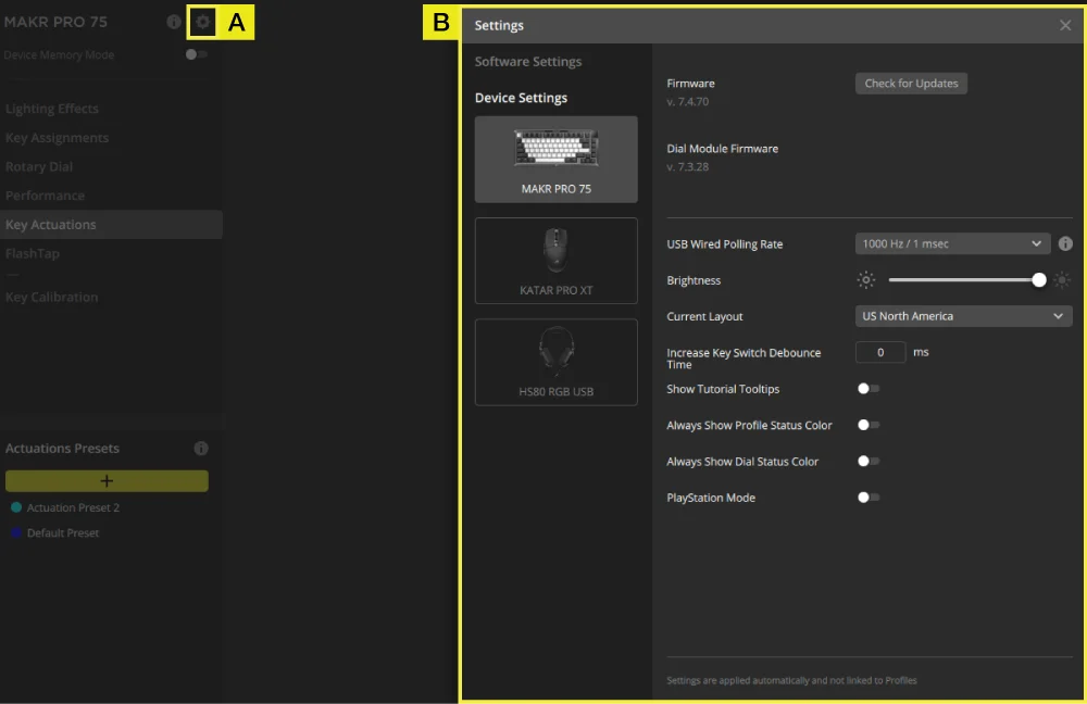
A. Kattintson a beállítás ikonra.
B. Módosítsa a speciális beállításokat (lekérdezési sebesség, fényerő...stb.).
MAKRÓFELVÉTEL
Az iCUE és a CORSAIR WEB HUB segítségével programozható.
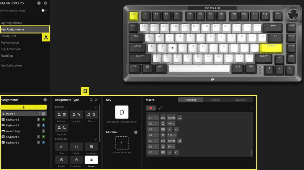
iCUE
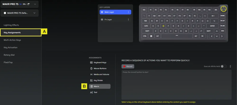
CORSAIR WEB HUB
A. Válassza ki a Billentyű-hozzárendelések lapot.
B. Kattintson a Hozzárendelés típusa menüben a Makró opcióra, majd a billentyűk átprogramozása után indítsa el a makrófelvételt.
GYÁRI BEÁLLÍTÁSOK VISSZAÁLLÍTÁSA
Tartsa lenyomva az ESC billentyűt, miközben kihúzza és visszadugja az USB Type-C kábelt, majd engedje fel az ESC billentyűt két másodperc elteltével. A billentyűzet ezután bekapcsol, a gyári beállítások visszaállnak.
AZ AKKUMULÁTOR KIVÉTELÉVEL KAPCSOLATOS TUDNIVALÓK
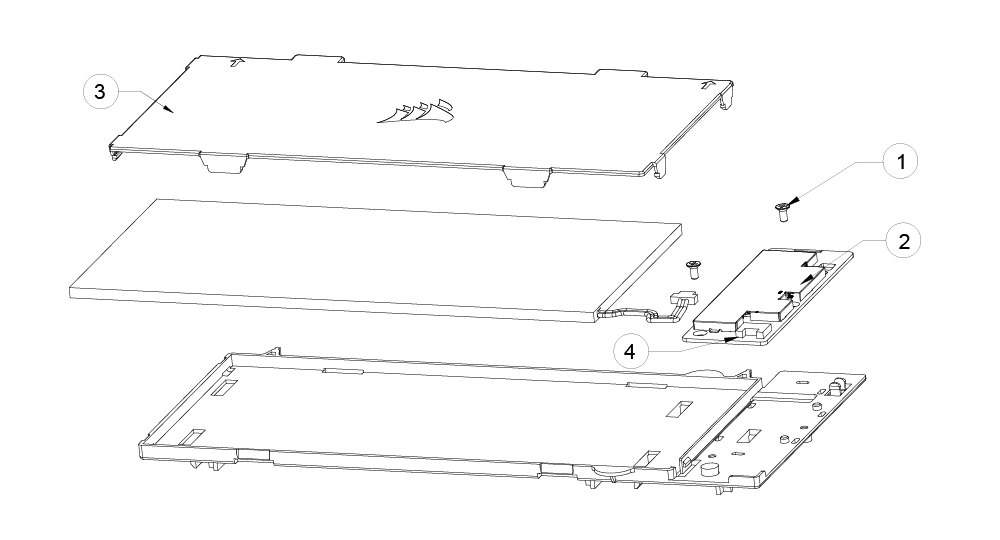
- Csavarozza ki a 2 db csavart a PCBA-ról
- Vegye ki a PCBA-t az akkumulátortartóból
- Vegye le az akkumulátor fedelét
- Vegye ki az akkumulátort a PCBA csatlakozóból
AKKUMULÁTORRA VONATKOZÓ INFORMÁCIÓK
- M/N (típusszám): 2670155
- Kapacitás (akkumulátor kapacitása): 3,7 V, 4170 mAh, 15,43 Wh
- Olvassa be a QR-kódot az akkumulátor adataiért

FCC-AZONOSÍTÓ: 2AAFM-RGP0175 (Vezeték nélküli modul)
FCC-azonosító: 2AAFM-RGP0146A (adapter)
IC: 10954A-RGP0175 (Vezeték nélküli modul)
IC: 10954A-RGP0146 (adapter)
M/N(型號): RGP0176
Értékelés(電壓電流): 5V
SZERZŐI JOG / JOGI INFORMÁCIÓK
A KDB 996369 D03 OEM kézikönyv szabályszakaszai:
2.2 Az alkalmazandó FCC-szabályok jegyzéke
Ezt a modult az FCC 15.247 és 15.249 szakaszának megfelelőségét illetően tesztelték
2.3 A konkrét üzemeltetési feltételek összefoglalása
A modul megfelelését az önálló, hordozható rádiófrekvenciás sugárzásnak való kitettségre vonatkozó használati feltételek szerint értékelik. Bármely egyéb használati feltétel – például más adókkal való együttes elhelyezés – esetén külön újraértékelésre van szükség, amelynek keretében II. osztályú engedélyezési módosítási kérelmet kell benyújtani, vagy új tanúsítást kell szerezni.
2.4 A modulok korlátozott eljárásai
Nem alkalmazandó.
2.6 Az RF-sugárzással kapcsolatos szempontok
Ez a berendezés megfelel az FCC által szabályozatlan környezetre vonatkozóan megállapított hordozható készülékekre vonatkozó sugárterhelési határértékeknek. A rádiófrekvenciás sugárterhelés tovább csökkenthető, ha a terméket a felhasználó testétől a lehető legnagyobb távolságra tartják.
2.7 Antennák
A következő antennák használata ezen modulhoz tanúsítvánnyal rendelkezik; az alábbiakban leírtak kivételével azonos típusú, azonos vagy kisebb erősítésű antennák is használhatók ezen modulhoz.
| Antenna-gyártó | Unictron Technologies Corp. |
| Antenna modell | CW801S |
| Antenna típus | Chipantenna |
| Antennaerősítés (dBi) | -4,07 |
| Antenna csatlakozó | N/A |
2.8 Címkézési és megfelelőségi információk
A végterméket jól látható helyen fel kell tüntetni a következő felirattal: „FCC-azonosító: 2AAFM-RGP0175”. A jogosult FCC-azonosítója csak akkor használható, ha az összes FCC-megfelelési követelmény teljesül.
Az OEM-integrátornak ügyelnie kell arra, hogy a modult tartalmazó végtermék felhasználói kézikönyvében ne adjon a végfelhasználónak információt a modul beszereléséről vagy eltávolításáról.
A végtermék használati útmutatójának tartalmaznia kell az ebben az útmutatóban szereplő összes előírt szabályozási információt és figyelmeztetést.
2.9 A vizsgálati módokra és a kiegészítő vizsgálati követelményekre vonatkozó információk
Ezt az adót önálló, hordozható rádiófrekvenciás sugárzási körülmények között vizsgálták meg; amennyiben más adó(k)kal egy helyen vagy egyidejűleg történik az adás, külön, II. osztályú engedélyezési módosításra vonatkozó újbóli értékelésre vagy új tanúsításra lesz szükség.
2.10 Kiegészítő vizsgálatok, 15. rész B. alrész – jogi nyilatkozat
Ezt az adómodult alrendszerként tesztelték, és tanúsítása nem terjed ki a végfelhasználói eszközre alkalmazandó FCC 15. rész B. alrész (véletlen sugárzó) szabályi követelményeire. A végfelhasználói eszközt adott esetben továbbra is újra kell értékelni a szabályi követelmények ezen részének való megfelelés szempontjából.
Az OEM-gyártók és a gazdagép-gyártók viselik a végső felelősséget a gazdagép és a modul megfelelőségéért. A végterméket az Egyesült Államok piacára történő forgalomba hozatal előtt újra kell értékelni az FCC-szabályzat valamennyi alapvető követelménye, például az FCC 15. rész B alrészének fényében. Ez magában foglalja az adómodul újraértékelését is az FCC-szabályzat rádió- és EMF-alapvető követelményeinek való megfelelés szempontjából. Ezt a modult nem szabad más eszközbe vagy rendszerbe beépíteni anélkül, hogy többrádiós és kombinált berendezésként újra megvizsgálnák a megfelelőségét.
Amennyiben a fenti feltételek mindegyike teljesül, további adótesztre nincs szükség. Az OEM-integrátor azonban továbbra is felelős a végtermék teszteléséért, hogy az a modul beépítése esetén is megfeleljen az esetleges további előírásoknak.
2.11 Megjegyzés: elektromágneses interferenciával kapcsolatos szempontok
Kérjük, kövesse a KDB 996369 D02 és D04 számú kiadványaiban a házgyártók számára megadott útmutatásokat.
2.12 Hogyan lehet módosításokat végrehajtani
Csak a licencbirtokosok végezhetnek engedélyezett módosításokat. Kérjük, vegye fel velünk a kapcsolatot, ha a modul beépítője a licencben foglaltaktól eltérő módon kívánja használni a modult: help.corsair.com
FONTOS MEGJEGYZÉS: Abban az esetben, ha ezek a feltételek nem teljesíthető (például bizonyos laptop-konfigurációk vagy egy másik adóval való egy helyszínen való elhelyezés esetén), akkor az FCC-engedély már nem tekinthető érvényesnek, és az FCC-azonosító nem tud a végtermékben felhasználásra kerül. Ilyen esetben az OEM-integrátor feladata a végtermék (beleértve az adót is) újbóli értékelése, valamint egy külön FCC-engedély beszerzése.
Ez az eszköz kizárólag OEM-integrátorok számára készült, az alábbi feltételek mellett: (Modulkénti használatra)
Az adómodul nem helyezhető el más adóval vagy antennával egy helyiségben.
Amennyiben a fenti feltételek teljesülnek, további adótesztre nincs szükség. Az OEM-integrátor azonban továbbra is felelős a végtermék teszteléséért, hogy az a modul beépítése esetén is megfeleljen az esetleges további előírásoknak.
Ez a készülék kizárólag OEM-integrátorok számára készült, az alábbi feltételek mellett: (Modulként való használatra)
Az adómodul nem helyezhető el más adóval vagy antennával együtt.
Amennyiben a fenti feltételek teljesülnek, az adóegység további tesztelésére nincs szükség. Az OEM-integrátor azonban továbbra is felelős a végtermék teszteléséért, amennyiben a beépített modulra vonatkozóan további megfelelőségi követelmények merülnek fel.
FONTOS MEGJEGYZÉS:
Amennyiben ezek a feltételek nem teljesülnek (például bizonyos laptop-konfigurációk vagy egy másik adóval való együttes elhelyezés esetén), a kanadai engedély érvényességét elveszíti, és az IC-azonosító nem használható a végterméken. Ilyen esetben az OEM-integrátor felel a végtermék (beleértve az adót is) újbóli értékeléséért és egy külön kanadai engedély megszerzéséért.
FONTOS MEGJEGYZÉS:
Amennyiben ezek a feltételek nem teljesülnek (például bizonyos laptop-konfigurációk vagy más adóval való együttes elhelyezés esetén), a kanadai engedély érvényességét elveszíti, és az IC-azonosító nem használható a végterméken. Ilyen körülmények között az OEM-integrátor feladata a végtermék (beleértve az adót is) újbóli értékelése és egy külön kanadai engedély megszerzése.
A végtermék címkézése
A terméket lehetőség szerint a felhasználó testétől távol kell tartani, vagy – amennyiben ilyen funkció áll rendelkezésre – a készüléket alacsonyabb kimeneti teljesítményre kell állítani. A végterméket jól látható helyen fel kell címkézni a következő felirattal: „IC:10954A-RGP0175-et tartalmaz.”
A végtermék típustáblája
A készüléket a felhasználó testétől a lehető legnagyobb távolságra kell tartani, vagy a készüléket a legalacsonyabb kimeneti teljesítményre kell beállítani, amennyiben ilyen funkció rendelkezésre áll. A végterméket jól látható helyen fel kell címkézni a következő felirattal: „IC-t tartalmaz: 10954A-RGP0175.”
Használati útmutató a végfelhasználó számára
Az OEM-integrátornak ügyelnie kell arra, hogy a modult tartalmazó végtermék használati útmutatójában ne adjon a végfelhasználónak információt a modul beszereléséről vagy eltávolításáról.
A végfelhasználói kézikönyvnek tartalmaznia kell az ebben a kézikönyvben szereplő összes előírt szabályozási információt és figyelmeztetést.
végfelhasználói kézikönyvAz OEM-integrátoroknak tudatában kell lenniük annak, hogy a modul beépítésére vagy eltávolítására vonatkozó információkat nem szabad megadniuk a végfelhasználónak a modult tartalmazó végtermék felhasználói kézikönyvében.
A végfelhasználói kézikönyvnek tartalmaznia kell az ebben a kézikönyvben megadott összes előírt szabályozási információt és figyelmeztetést.
© 2025–2026 CORSAIR MEMORY, Inc. Minden jog fenntartva. A CORSAIR és a vitorlás logó a CORSAIR bejegyzett védjegyei az Egyesült Államokban és/vagy más országokban. Minden egyéb védjegy a megfelelő tulajdonosok tulajdonát képezi. A termék a képen láthatótól kissé eltérhet.