-
ESPECIFICAÇÕES DA CAIXA
-
CONTEÚDO DO KIT DE ACESSÓRIOS
-
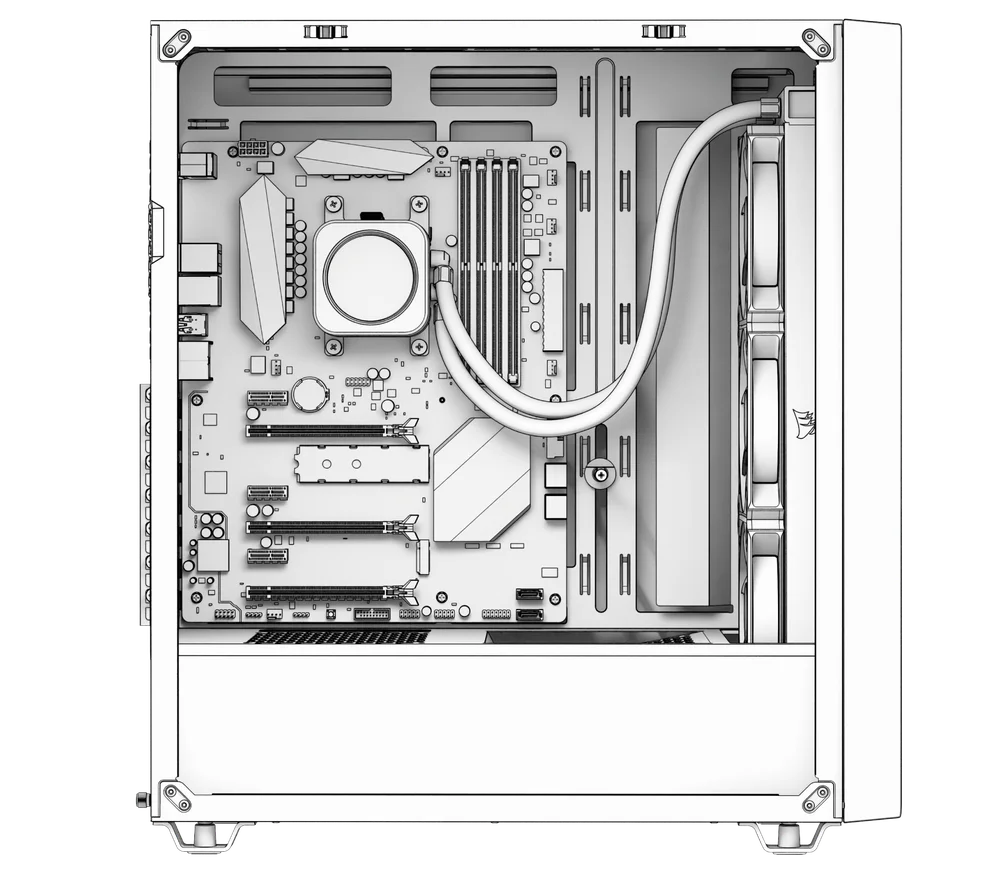
VISUALIZAÇÃO AMPLIADA DA CAIXA
-
INSTALAÇÃO / REMOÇÃO DE PAINÉIS
-
INSTALAÇÃO DA PLACA-MÃE
-
INSTALAÇÃO DOS CABOS DE E/S FRONTAIS
-
INSTALAÇÃO DO VENTILADOR
-
INSTALAÇÃO DE RADIADORES
-
INSTALAÇÃO DE DISPOSITIVOS DE ARMAZENAMENTO E CONTROLADORES
-
INSTALAÇÃO DA FONTE DE ALIMENTAÇÃO
-
INSTALAÇÃO DA PLACA GRÁFICA
-
CONECTAR OS SEUS FÃS
-
MANUTENÇÃO
-
DECLARAÇÃO DE GARANTIA
-
LISTA DE PEÇAS DE SUBSTITUIÇÃO
- CONTEÚDO RELACIONADO
MANUAL | GUIA DE INÍCIO RÁPIDO
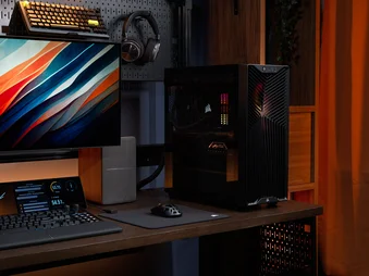
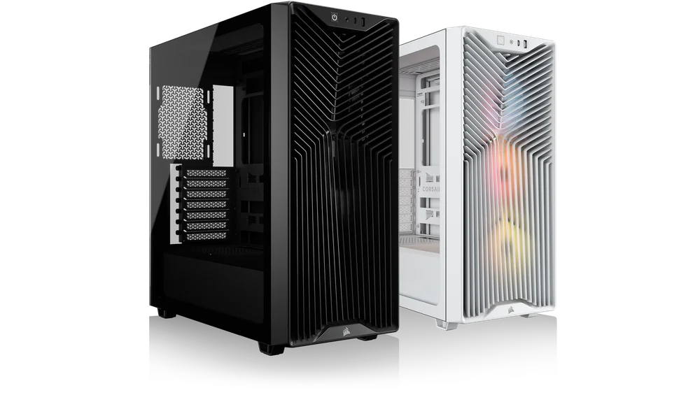
CORSAIR 3200D
CAIXA DE ORGANIZADOR DE MÉDIO TAMANHO
A versão em inglês está disponível aqui - English
Se você tiver qualquer outro problema entre em contato suporte ao cliente
ESPECIFICAÇÕES DA CAIXA
|
Configuração da ranhura PCI |
7 Horizontal |
|
Compatibilidade com placas-mãe |
Mini-ITX, Micro-ATX, ATX |
|
Discos rígidos |
1x |
|
SSD |
3x |
|
Cores disponíveis |
Preto, Branco, Cinza |
|
Material do painel lateral esquerdo |
Vidro temperado |
|
Espaço para cabos na parte traseira |
24 mm |
|
Filtros de pó |
Frente, Parte superior, Fonte de alimentação |
|
Portas de E/S frontais |
1 porta USB 2.0 Tipo A 1 porta USB 3.2 Gen 2x2 Tipo C 1x PWR 1 conjunto de microfone e auscultadores |
1. Localização dos ventiladores
|
Frente |
Topo |
Traseira |
Lateral |
Capa da fonte de alimentação | Parte inferior | |
|
3 unidades de 120 mm 2 unidades de 140 mm |
3 unidades de 120 mm 2 unidades de 140 mm |
1 unidade de 120 mm |
Nenhum |
2 unidades de 120 mm |
Nenhum |
|
2. VENTILADORES E CONTROLADORES INCLUÍDOS
|
3200D RS |
3200D RS ARGB |
Controladores incluídos |
|
3 unidades RS120 pré-instaladas |
3 unidades RS120 ARGB pré-instaladas | Nenhum |
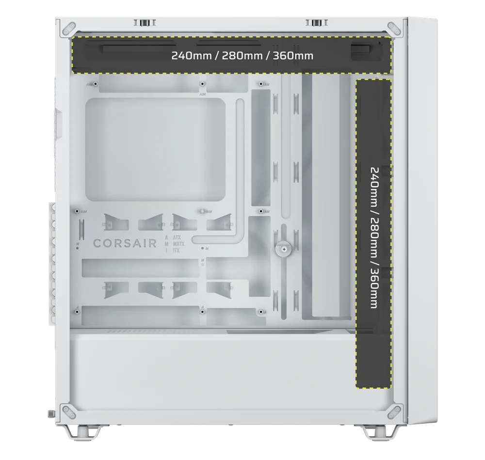
3. COMPATIBILIDADE DO RADIADOR
|
Frente |
Topo |
Traseira |
Lateral |
Capa da fonte de alimentação |
|
240 mm 280 mm 360 mm |
240 mm 280 mm 360 mm |
Nenhum |
Nenhum |
Nenhum |
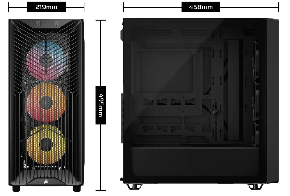
4. DIMENSÕES DA CAIXA
| Dimensões |
458 mm x 219 mm x 495 mm |
|
Comprimento máximo da GPU |
375 mm com ventoinha / 400 mm sem ventoinha |
|
Altura máxima do dissipador da CPU |
165 mm |
|
Comprimento máximo da fonte de alimentação |
180 mm |
CONTEÚDO DO KIT DE ACESSÓRIOS
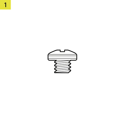
18 parafusos para placa-mãe/HDD (6-32 UNC; 6 mm)

12 parafusos para SSD (M3 x 0,5; 5 mm)
1 suporte de reserva para placa-mãe
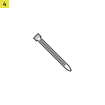
12 abraçadeiras
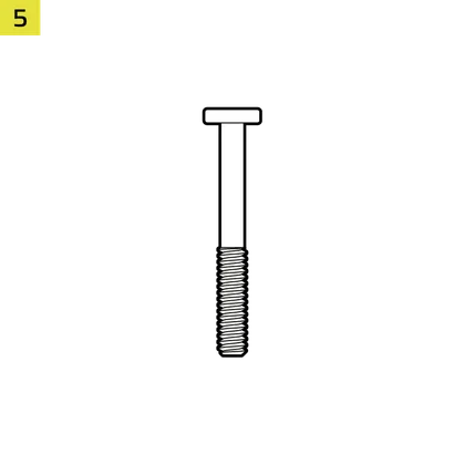
8 parafusos longos para ventoinha
1 espaçador de borracha para braço de estabilização anti-afundamento
3 ventoinhas RS120/RS120 ARGB
(pré-instaladas)

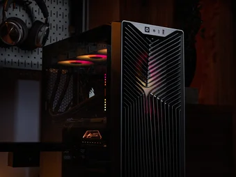
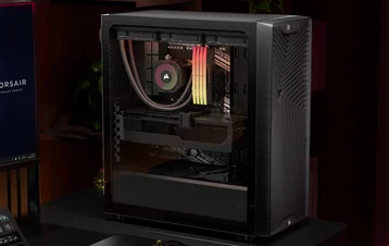
VISUALIZAÇÃO AMPLIADA DA CAIXA
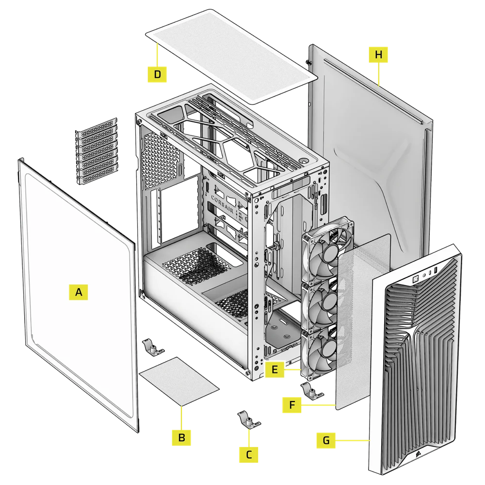
| A. Painel lateral em vidro temperado | E. Ventiladores frontais |
| B. Filtro do ventilador da fonte de alimentação | F. Filtro do ventilador dianteiro |
| C. Pés | G. Painel frontal |
| D. Filtro superior | H. Painel lateral em aço |
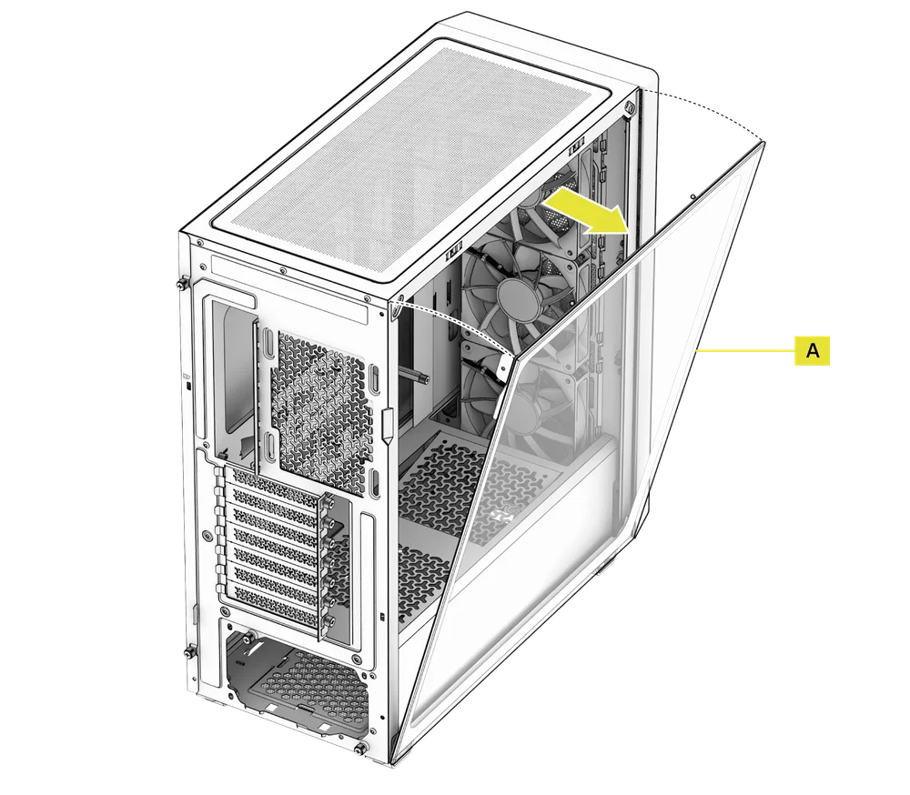
INSTALAÇÃO / REMOÇÃO DE PAINÉIS
AVISO: Este produto contém vidro temperado. Manuseie com cuidado.
- Para evitar danos ou ferimentos, evite colocar ou guardar a mala sobre superfícies duras, como azulejos de cerâmica ou porcelana, pedra, alvenaria ou betão.
- A CORSAIR recomenda vivamente que retire todos os painéis laterais de vidro temperado antes de colocar a caixa ou de iniciar a montagem sobre uma superfície dura.
- Se for necessário colocar o equipamento montado sobre uma superfície dura, eleve ou isole a caixa para minimizar o risco de contacto acidental, danos ou ferimentos.
- Os painéis de vidro temperado incluem uma película anti-estilhaçamento por motivos de segurança. Não retire esta película de segurança do vidro, pois isso danificará o painel.
Estão disponíveis painéis de substituição em www.corsair.com. Contacte help.corsair.com caso necessite de assistência.
1. REMOÇÃO DO PAINEL LATERAL DE VIDRO TEMPERADO
O painel lateral de vidro temperado 3200D (A) é fixado por dois fechos de bola na parte superior e preso com um parafuso na parte traseira.
- Desaparafuse o painel lateral de vidro temperado (A) na parte traseira da caixa.
- Puxe a parte superior do painel para fora, incline-o em direção ao chão e, em seguida, retire-o da lateral da caixa.
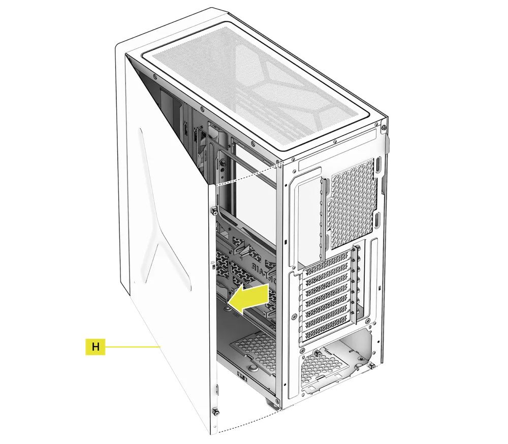
2. REMOÇÃO DO PAINEL LATERAL DE AÇO
O painel lateral de aço 3200D (H) é fixado por um fecho de mola na parte inferior e preso com dois parafusos de aperto manual na parte traseira.
- Desaparafuse o painel lateral de aço (H) na parte traseira da caixa.
- Balança a parte traseira do painel para fora e retira-o da lateral da caixa.
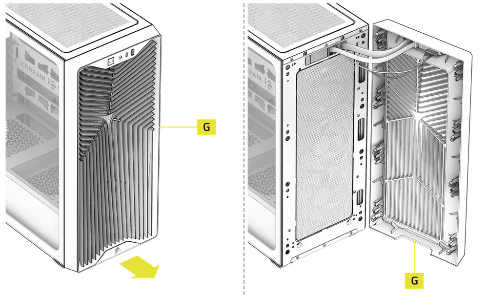
3. REMOÇÃO DO PAINEL FRONTAL
- Puxe o painel frontal (G) para fora, a partir da parte inferior. Está preso por oito fechos de pressão.
AVISO: Evite fazer alavanca, torcer ou forçar o painel frontal, pois isso pode sobrecarregar os clipes de fixação e danificar o painel. Os cabos de E/S frontais também estão ligados, por isso tenha isso em atenção ao puxar o painel para fora.
4. REMOÇÃO DAS ENTRADAS E SAÍDAS DO PAINEL FRONTAL
A E/S do painel frontal é fixada na parte superior interna do painel frontal (G) com três parafusos.
- Para o remover, basta desaparafusar os parafusos e todo o conjunto de E/S do painel frontal pode ser retirado.
- Para reinstalar o painel frontal de E/S ou instalar um novo, volte a colocar o conjunto na sua posição e fixe-o com os mesmos parafusos.
INSTALAÇÃO DA PLACA-MÃE
INSTALAÇÃO DE UMA PLACA-MÃE
O 3200D é compatível com placas-mãe mITX, mATX e ATX, incluindo as séries ASUS BTF, MSI Project Zero e GIGABYTE Project Stealth com ligações de alimentação invertidas.
- Alinhe a placa-mãe com os espaçadores e fixe-a com os parafusos para placa-mãe fornecidos (1).
NOTA: Antes da instalação, certifique-se de que a placa de proteção de E/S da placa-mãe está colocada, se necessário.
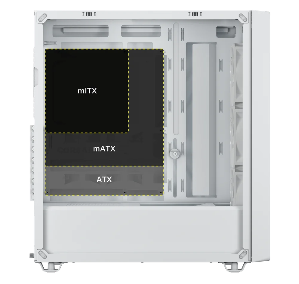
DICA: Se os espaçadores pré-instalados não se alinharem com os orifícios da placa-mãe, remova os que não forem utilizados e reposicione-os de modo a corresponderem aos pontos de montagem disponíveis na placa-mãe.
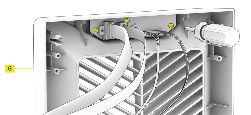
INSTALAÇÃO DOS CABOS DE E/S FRONTAIS
1. PLACAS-MÃE INTEL PADRÃO
- Ligue o conector FPANEL ao conector de E/S do painel frontal da placa-mãe, alinhando-o com o padrão de encaixe. Este conector é frequentemente identificado como JFP1 em algumas placas-mãe.
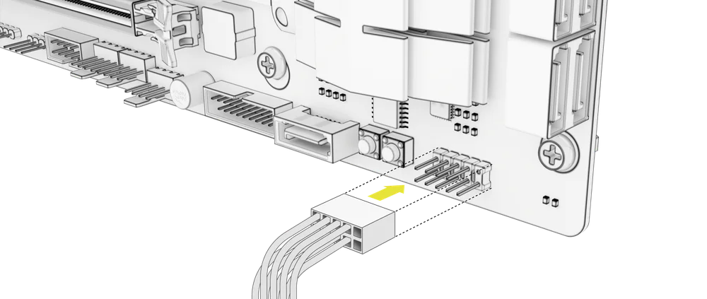
NOTA: Consulte o manual do produto da sua placa-mãe para obter informações sobre a disposição dos pinos.
2. EXPLICAÇÃO DAS ENTRADAS/SAÍDAS FRONTAIS
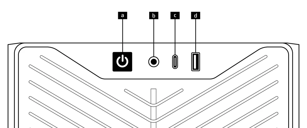
| a.Botão de ligar/desligar + LED | c. 1 porta USB 3.2 Gen 2x2 Tipo C (20 Gbps) |
| b.Tomada combinada para auscultadores e microfone | d. 1 porta USB 2.0 Tipo A |
3. Ligações de E/S frontais
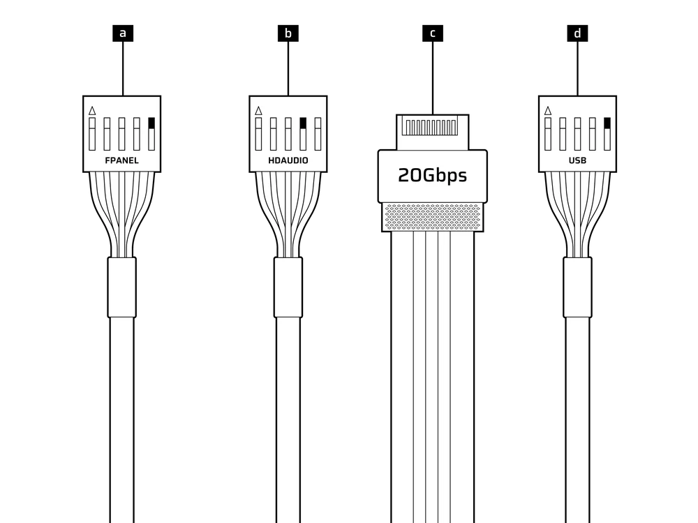
| a. FPANEL (LED de alimentação, botão de alimentação) | c. USB 3.2 Tipo E (20 Gbps) |
| b. Áudio HD (auscultadores, microfone) | d. USB 2.0 |
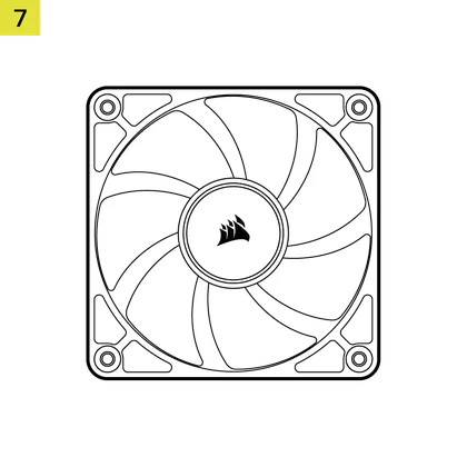
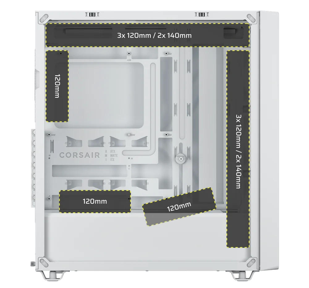
INSTALAÇÃO DO VENTILADOR
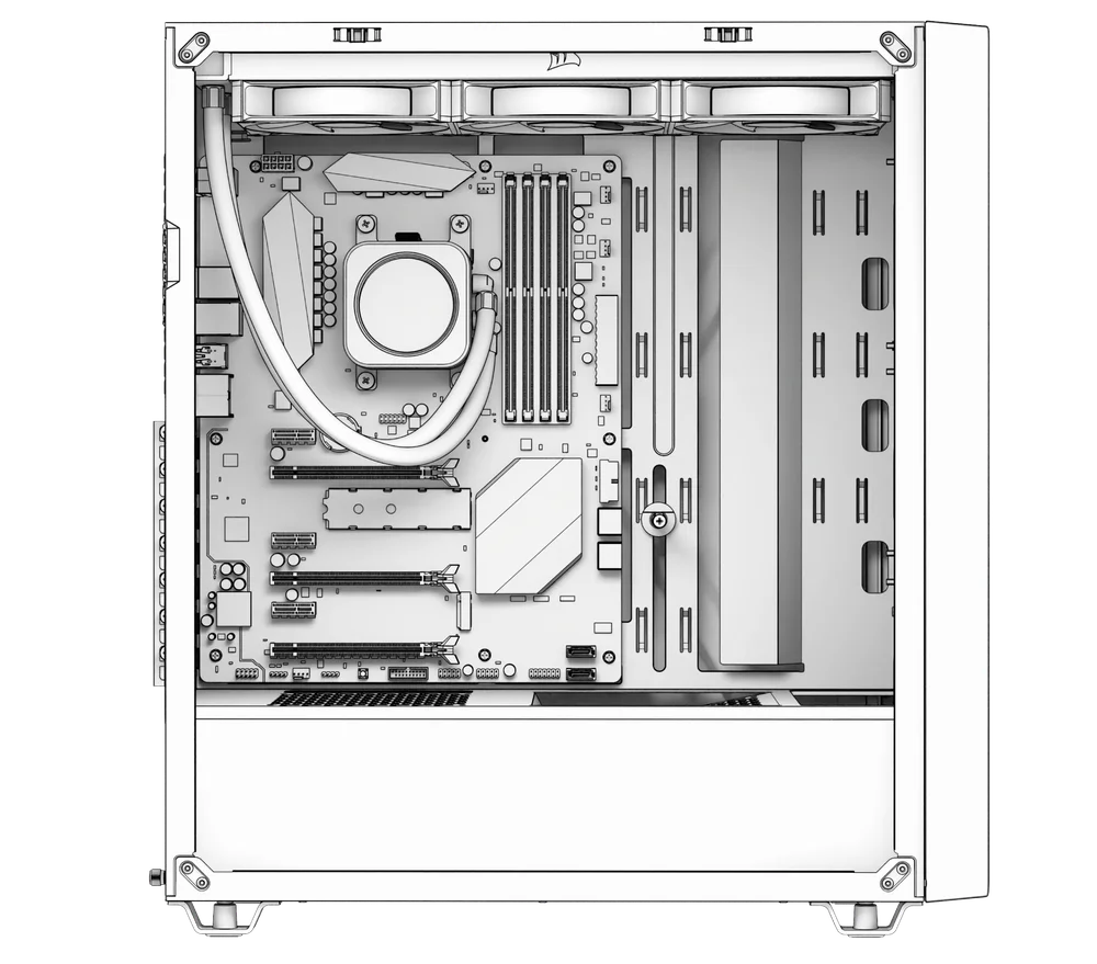
O 3200D permite a instalação de até 9 ventoinhas de 120 mm ou 4 ventoinhas de 140 mm na parte superior, lateral e traseira da caixa.
|
Frente |
Topo |
Traseira |
Lateral |
Capa da fonte de alimentação | Parte inferior | |
|
3 unidades de 120 mm 2 unidades de 140 mm |
3 unidades de 120 mm 2 unidades de 140 mm |
1 unidade de 120 mm |
Nenhum |
2 unidades de 120 mm |
Nenhum |
|
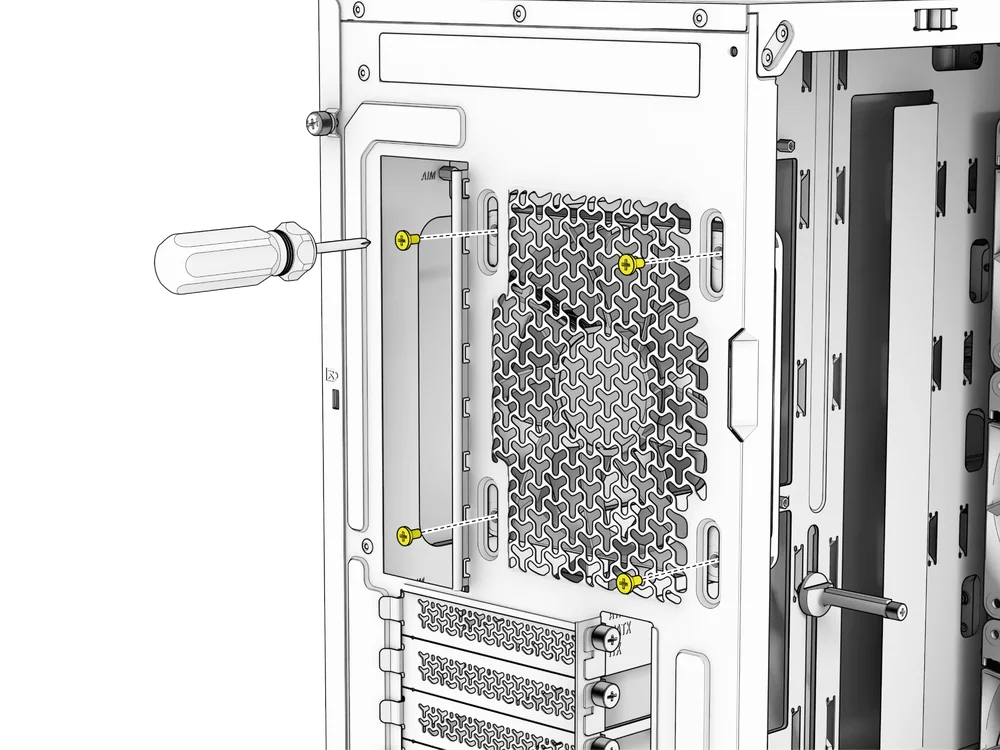
1. INSTALAÇÃO DE VENTILADORES NA PARTE SUPERIOR E NA FRENTE
- Alinhe as ventoinhas com as posições de montagem e fixe-as utilizando os parafusos fornecidos com as ventoinhas.
NOTA: Se perdeu os parafusos da ventoinha, a CORSAIR disponibiliza parafusos personalizados concebidos para ventoinhas que utilizam parafusos de montagem auto-roscantes de plástico. Os parafusos personalizados da CORSAIR para ventoinhas estão disponíveis na loja online.
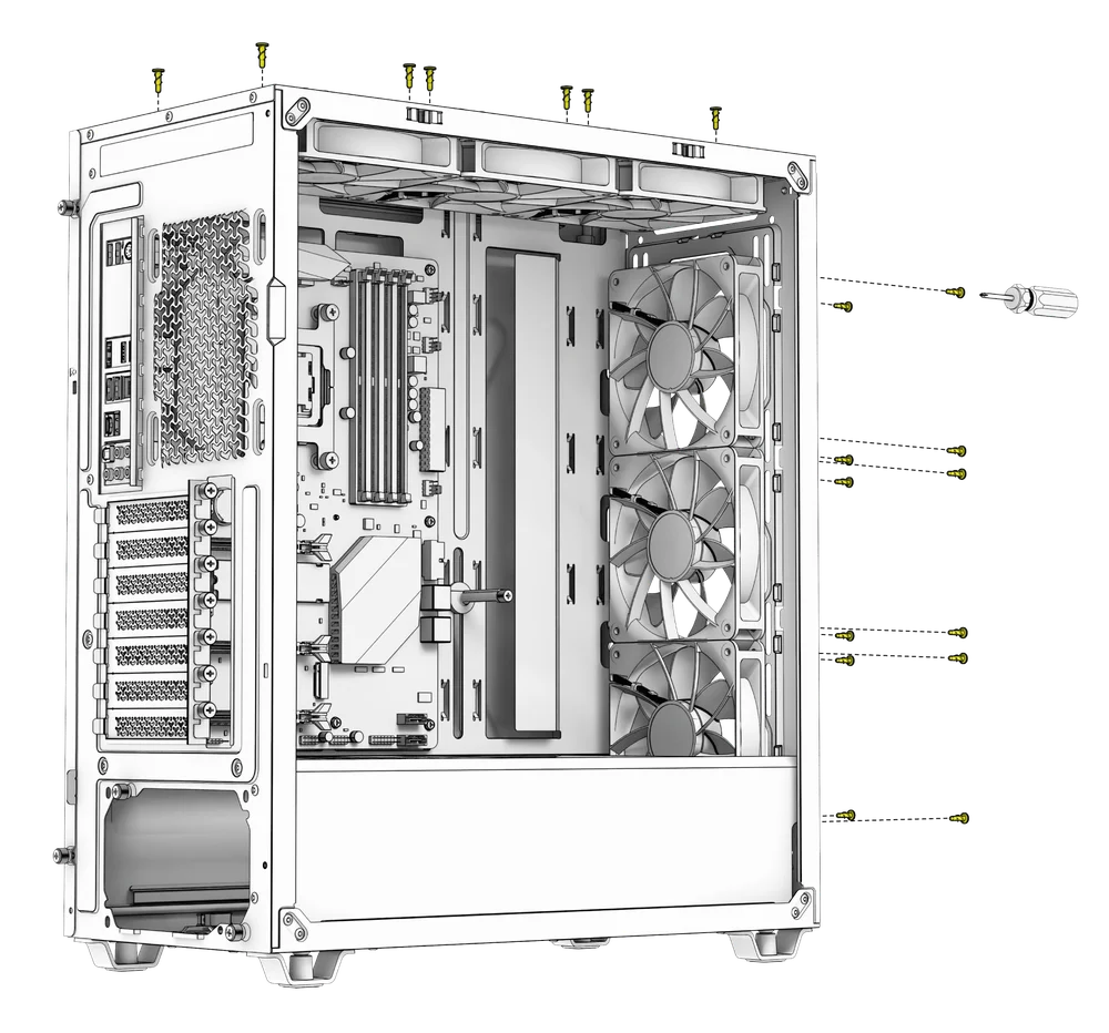
DICA: Utilize os pontos marcados na base lateral do ventilador como guias de centralização.
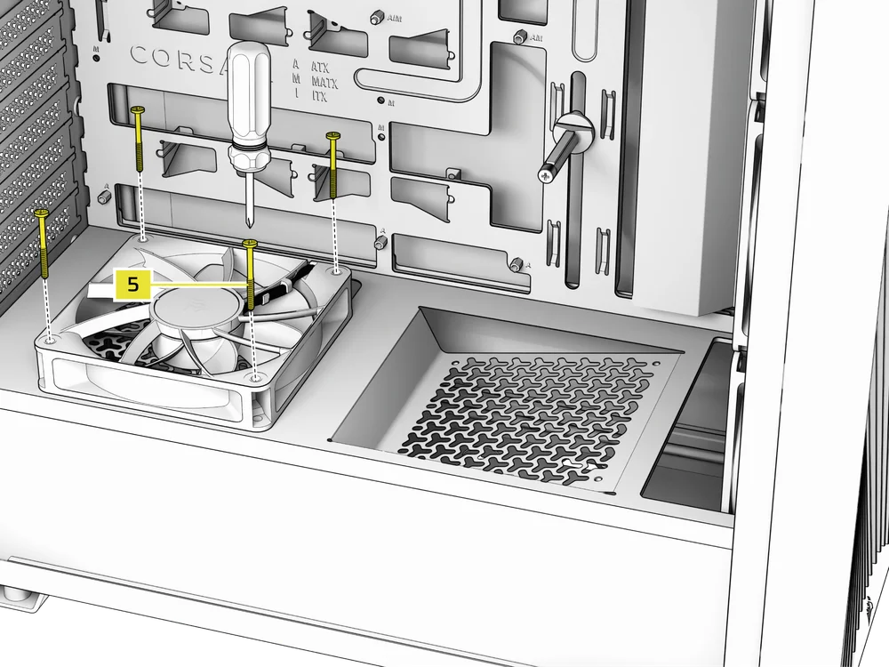
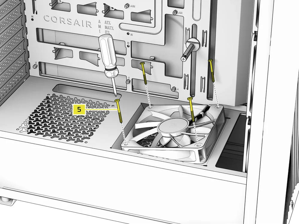
2. INSTALAÇÃO DE VENTILADORES NA COBERTURA DA FONTE DE ALIMENTAÇÃO
- Alinhe as ventoinhas com os orifícios de montagem da cobertura da fonte de alimentação.
- Prenda as ventoinhas com os parafusos longos para ventoinhas (5) a partir da parte superior.
3. INSTALAÇÃO DE UMA VENTILADORA NA PARTE TRASEIRA
- Alinhe a ventoinha com os orifícios de montagem da ventoinha.
- Utilize os parafusos fornecidos com a ventoinha para a fixar à caixa.
INSTALAÇÃO DE RADIADORES
O modelo 3200D possui pontos de fixação integrados para a instalação de ventoinhas e radiadores em toda a caixa.
DICA: Para obter um desempenho ideal em termos de ruído, temperatura e fiabilidade, certifique-se de que o radiador está montado mais alto do que a bomba ao utilizar um sistema de refrigeração líquido «tudo-em-um» (AIO) para a CPU.
NOTA: O modelo 3200D não suporta a utilização simultânea de vários radiadores de 360 mm.
|
Frente |
Topo |
Traseira |
Lateral |
Capa da fonte de alimentação |
|
240 mm 280 mm 360 mm |
240 mm 280 mm 360 mm |
Nenhum |
Nenhum |
Nenhum |
1. INSTALAÇÃO DE UM RADIADOR NA PARTE SUPERIOR
A montagem na parte superior proporciona um desempenho acústico ideal, mas podem ser utilizadas outras formas de montagem, consoante as suas preferências de montagem. Consulte o manual do produto do seu dissipador para obter mais dicas sobre a utilização e as melhores práticas.
NOTA: Os módulos de memória de altura padrão ou elevada podem interferir na instalação do radiador na parte superior da caixa. Recomenda-se instalar o radiador e as ventoinhas antes de instalar a memória.
IMPORTANTE: Para instalar um radiador na parte superior com ventoinhas à frente e atrás, recomenda-se remover a ventoinha traseira e a ventoinha frontal superior antes da instalação do radiador, para garantir a máxima facilidade de manobra. A saída de ar traseira pode ser removida caso pretenda espaço adicional para a tubagem do AIO.
2. INSTALAÇÃO DE UM RADIADOR NA PARTE DA FRENTE
INSTALAÇÃO DE DISPOSITIVOS DE ARMAZENAMENTO E CONTROLADORES
O 3200D oferece espaço para a instalação de dois SSDs atrás da bandeja da placa-mãe e de um HDD ou um SSD na parte inferior do gabinete.
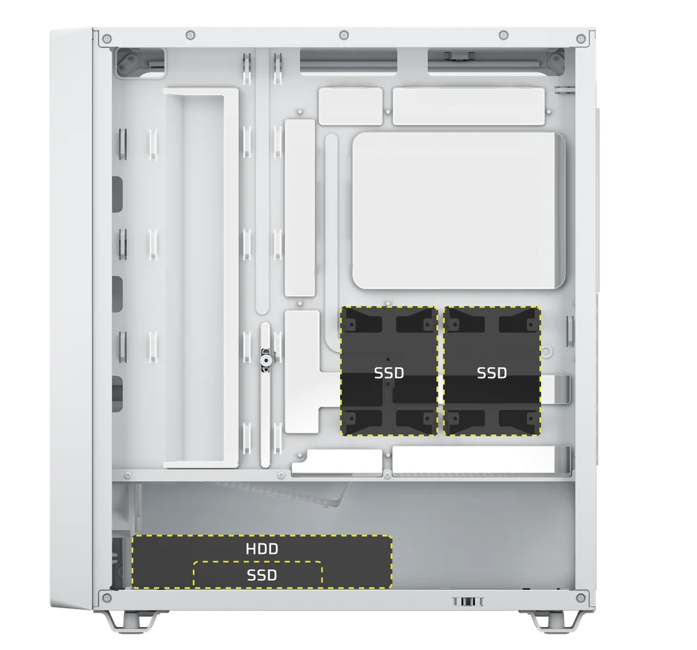
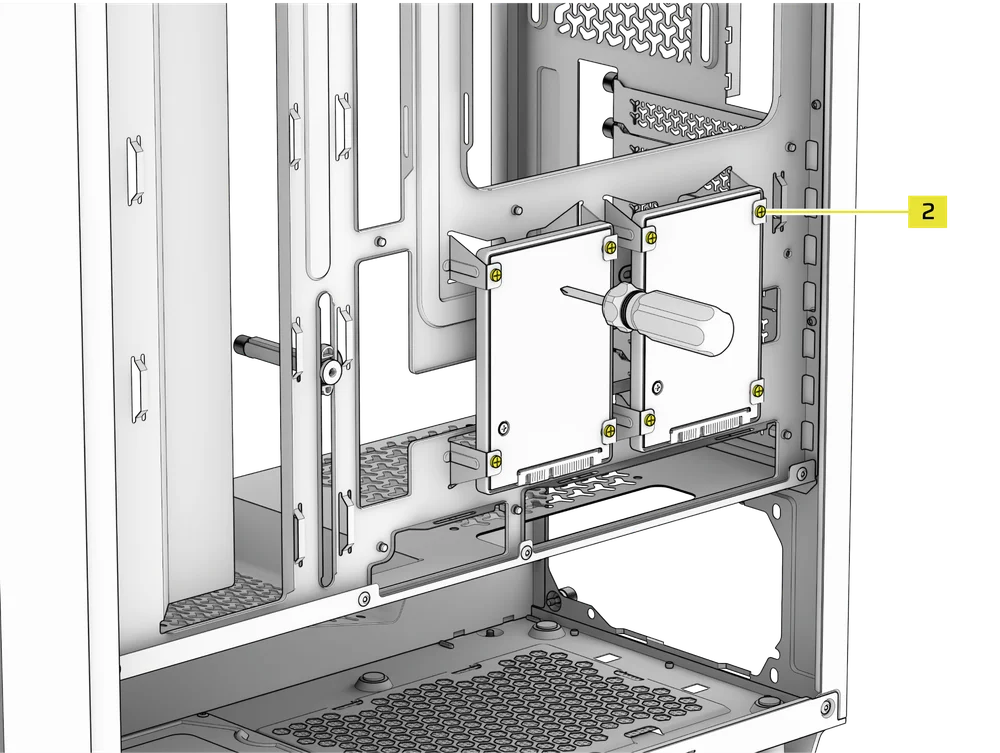
1. INSTALAÇÃO DE UM SSD
- Fixe o(s) SSD(s) na parte traseira da bandeja da placa-mãe com os parafusos para SSD incluídos (2).
NOTA: É possível instalar um terceiro SSD na parte inferior da caixa. Este é também o único local de montagem disponível para um HDD, pelo que a instalação de um terceiro SSD impedirá a instalação de um HDD.
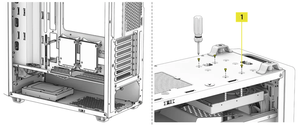
3. INSTALAÇÃO DE UM DISCO RÍGIDO
- Vire a caixa de cabeça para baixo para aceder aos orifícios de montagem do disco rígido.
- Fixe o disco rígido na parte inferior da caixa utilizando os parafusos para a placa-mãe/disco rígido incluídos (1).
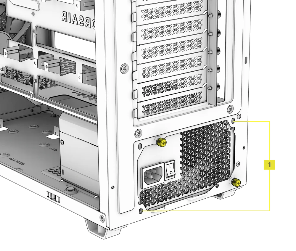
INSTALAÇÃO DA FONTE DE ALIMENTAÇÃO
1. INSTALAÇÃO DA FONTE DE ALIMENTAÇÃO PADRÃO
- Instale a fonte de alimentação com a ventoinha virada para baixo.
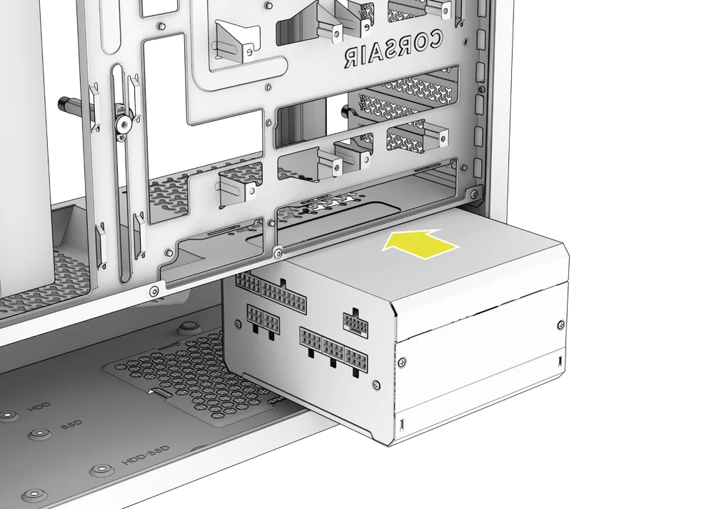
- Prenda a fonte de alimentação ao chassis com os dois parafusos de fixação localizados na parte traseira da caixa.
- Para maior segurança, fixe a fonte de alimentação utilizando dois parafusos da placa-mãe (1) nos cantos do painel traseiro.
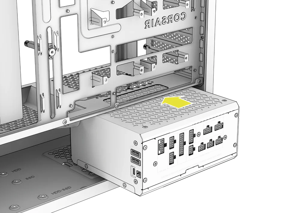
2. INSTALAÇÃO DA FONTE DE ALIMENTAÇÃO CORSAIR SHIFT
As fontes de alimentação CORSAIR SHIFT possuem ligações laterais para facilitar o acesso durante a montagem e as atualizações. O modelo 3200D foi concebido a pensar na série SHIFT, oferecendo espaço suficiente para dobrar e passar os cabos. O recorte alargado no painel lateral é compatível tanto com as fontes de alimentação SHIFT como com placas-mãe com conectores invertidos.
As fontes de alimentação CORSAIR SHIFT instalam-se exatamente da mesma forma que uma fonte de alimentação ATX padrão.
NOTA: O modelo 3200D suporta fontes de alimentação SHIFT com até 180 mm de comprimento.
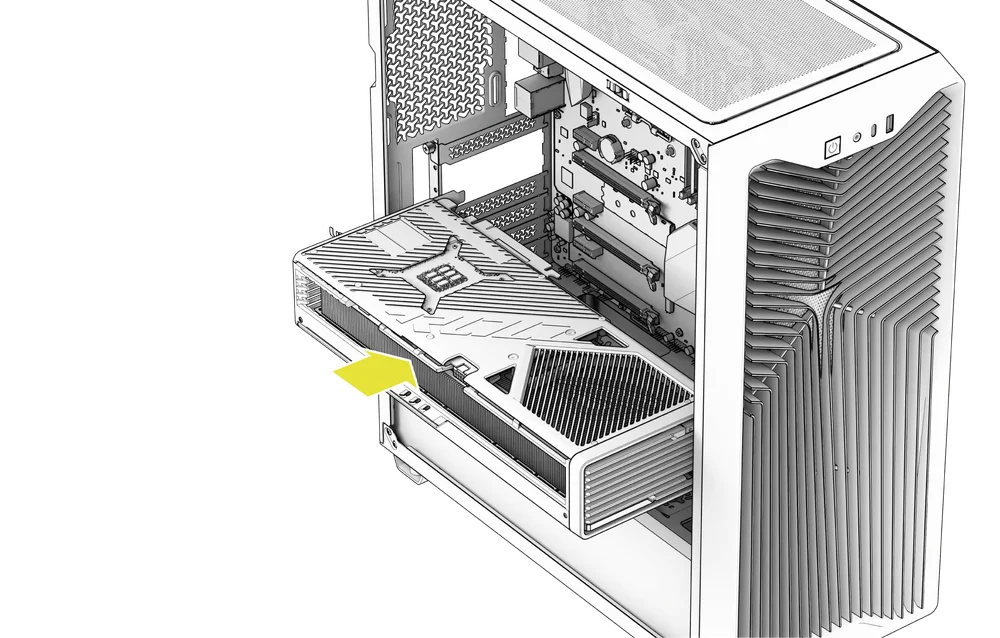
INSTALAÇÃO DA PLACA GRÁFICA
O 3200D suporta nativamente apenas instalações horizontais da GPU.
DICA: Para facilitar a montagem, instale a GPU no final.
1. INSTALAÇÃO DA PLACA GRÁFICA
- Desaparafuse as tampas das ranhuras PCIe e retire-as.
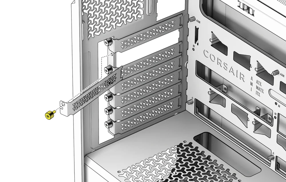
- Insira a placa na ranhura PCIe até ouvir um clique, indicando que encaixou no mecanismo de retenção da ranhura.
- Alinhe o suporte com as ranhuras PCIe e fixe a placa ao gabinete.
2. UTILIZAÇÃO DO BRAÇO DE ESTABILIZAÇÃO ANTI-AFUNDAMENTO DA GPU
O Braço de Estabilização Anti-afundamento para GPU apoia a sua placa gráfica, impedindo que esta se dobre ou afunde sob o peso do dissipador de calor. Isto não só ajuda a proteger a sua placa gráfica e a ranhura PCIe, como também contribui para uma montagem mais organizada e com um aspeto mais profissional.
- Ajuste o braço de estabilização anti-afundamento da GPU, desapertando o parafuso de aperto manual situado na parte frontal e deslizando o braço para cima ou para baixo.
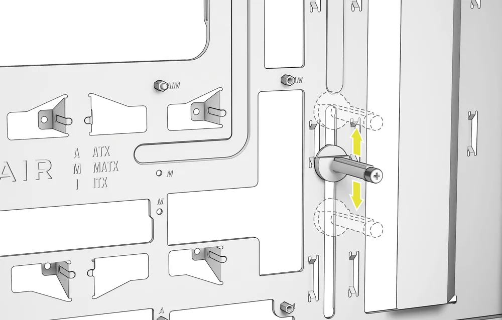
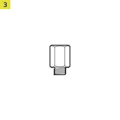
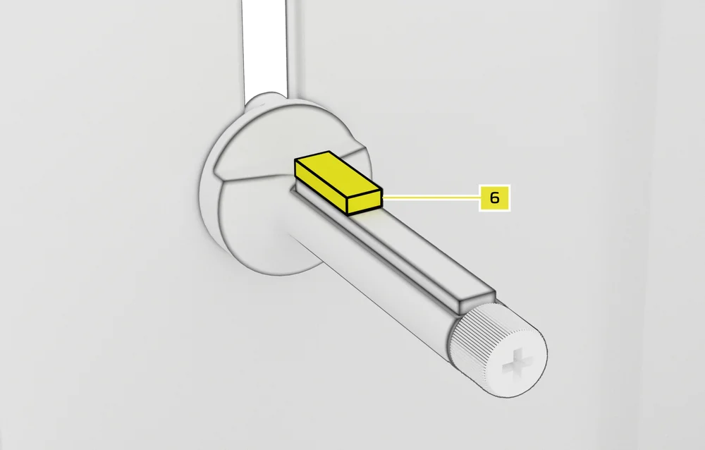
NOTA: Se a ventoinha da GPU ou outras peças entrarem em contacto com o braço, utilize o espaçador de borracha para estabilização anti-afundamento do braço (6), incluído na caixa de acessórios, para garantir que não haja contacto com quaisquer peças móveis.
- Fixe o espaçador de borracha autoadesivo do braço de estabilização anti-afundamento (6) ao braço anti-afundamento da GPU.
CONECTAR OS SEUS FÃS
1. LIGAÇÃO E CONTROLO DAS VENTILADORAS DO 3200D RS
Consulte o Guia de Início Rápido da Série CORSAIR RS para obter instruções sobre a instalação das ventoinhas.
2. LIGAÇÃO E CONTROLO DAS VENTILADORAS DO 3200D RS ARGB
Consulte o Guia de Início Rápido da Série CORSAIR RS ARGB para obter instruções sobre a instalação das ventoinhas.
MANUTENÇÃO
1. LIMPEZA DOS FILTROS DA CAIXA
O modelo 3200D inclui três filtros de pó removíveis: um filtro de alimentação de encaixe na parte inferior, um filtro magnético na parte superior e um filtro de encaixe na parte frontal.
- Para remover o filtro da ventoinha frontal (F), retire primeiro o painel frontal (G) e incline-o para o lado.
- Retire o filtro.
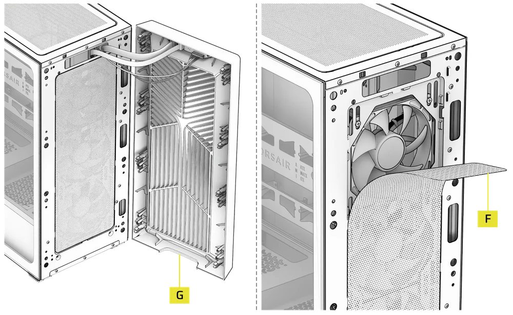
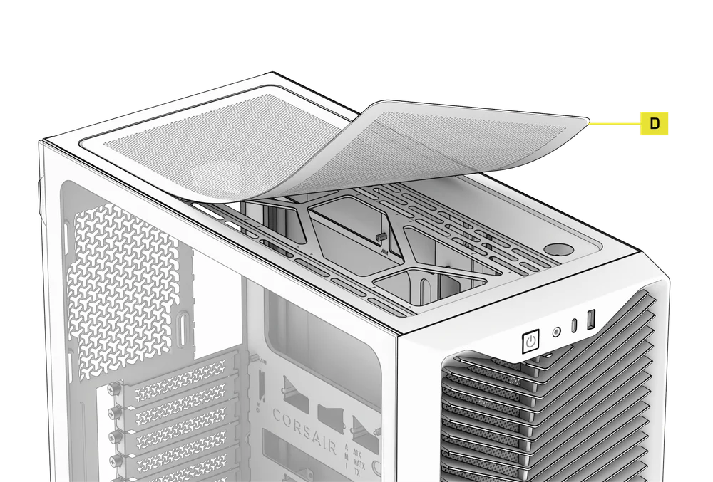
- Para retirar o filtro superior magnético (D), basta levantá-lo da caixa.
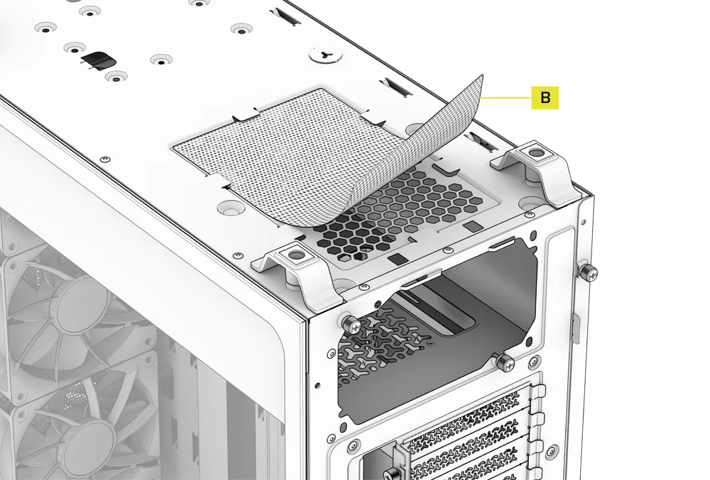
- Para remover o filtro da ventoinha da fonte de alimentação (B), comece por virar a caixa ao contrário.
- Aperte suavemente a malha do filtro pelas bordas para a soltar das patilhas e, em seguida, puxe-a para fora.
NOTA: Os filtros podem ser limpos com ar comprimido ou água. Se enxaguar o filtro, certifique-se de que este está completamente seco antes de o voltar a instalar.
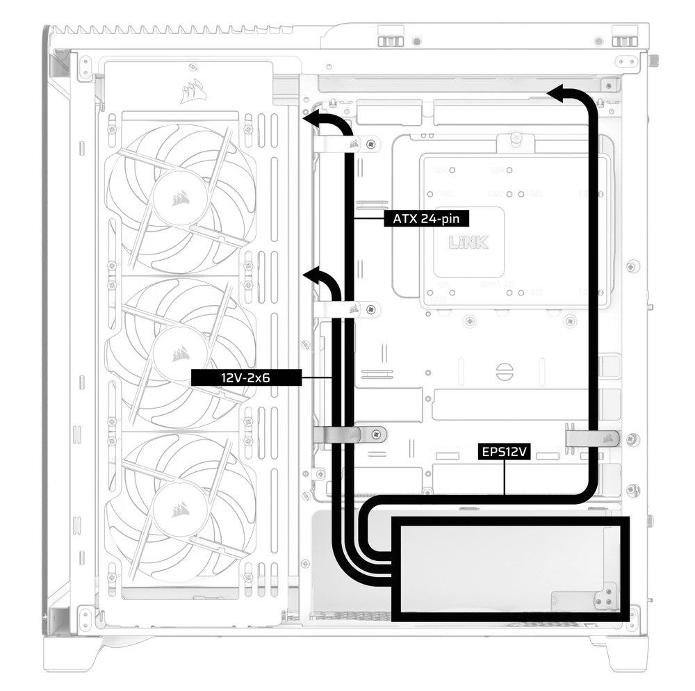
2. DICAS PARA A ORGANIZAÇÃO DE CABOS
O 3200D inclui várias funcionalidades de gestão de cabos, tais como:
- Várias posições para as tiras de velcro, para acomodar placas-mãe com conectores padrão ou invertidos.
- Os pontos de fixação com abraçadeiras estão estrategicamente posicionados para o encaminhamento dos cabos de alimentação até dispositivos específicos.
- Compatível com a maioria das placas-mãe com conectores traseiros (MSI, ASUS, GIGABYTE) que possuem conectores na parte traseira da placa, permitindo uma montagem sem cabos visíveis da placa-mãe.
DECLARAÇÃO DE GARANTIA

As caixas CORSAIR 3200D têm uma garantia de 2 anos.
LISTA DE PEÇAS DE SUBSTITUIÇÃO
| CC-8901191 |
Conjunto do painel frontal de substituição 3200D, preto
|
| CC-8901192 |
Conjunto do painel frontal de substituição 3200D, branco
|
| CC-8901193 |
Conjunto do painel frontal de substituição 3200D, cor fumada
|
| CC-8901194 |
Conjunto de filtros de substituição 3200D (parte superior/frente/fonte de alimentação), preto
|
| CC-8901195 |
Conjunto de filtros de substituição 3200D (parte superior/frente/fonte de alimentação), branco
|
| CC-8901196 |
Painel lateral de substituição em aço perfurado 3200D, preto
|
| CC-8901197 |
Painel lateral de substituição em aço perfurado 3200D, branco
|
| CC-8901198 |
Painel lateral de vidro temperado de substituição 3200D, preto
|
| CC-8901199 |
Painel lateral de vidro temperado de substituição 3200D, branco
|
| CC-8901200 |
Painel frontal de substituição 3200D para E/S, preto
|
| CC-8901201 |
Painel frontal de substituição 3200D para E/S, branco
|
| CC-8901202 |
Caixa de acessórios de substituição 3200D, preta
|
| CC-8901203 |
Caixa de acessórios de substituição 3200D, branca
|
| CC-8901204 |
Conjunto de pés de substituição 3200D, preto
|
| CC-8901205 |
Conjunto de pés de substituição 3200D, branco
|
CONTEÚDO RELACIONADO