-
CASE SPECIFICATIONS
-
ACCESSORY KIT CONTENTS
-
CASE EXPANDED VIEW
-
PANEL INSTALLATION / REMOVAL
-
MOTHERBOARD INSTALLATION
-
MAGNETIC STRIP INSTALLATION
-
FRONT PANEL I/O CABLES INSTALLATION
-
FAN INSTALLATION
-
HYDRO X CUSTOM COOLING SUPPORT
-
RADIATOR INSTALLATION
-
INSTALLATION OF STORAGE DEVICES AND CONTROLLERS
-
POWER SUPPLY INSTALLATION
-
GRAPHICS CARD INSTALLATION
-
CONNECTING YOUR FANS
-
MAINTENANCE
-
SPARE PARTS LISTING
-
WARRANTY
-
LEGAL
- RELATED CONTENT
MANUAL | QUICK START GUIDE
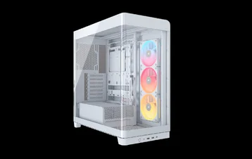
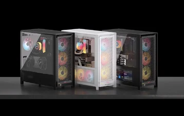
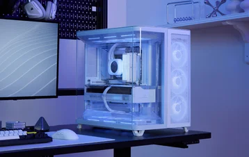
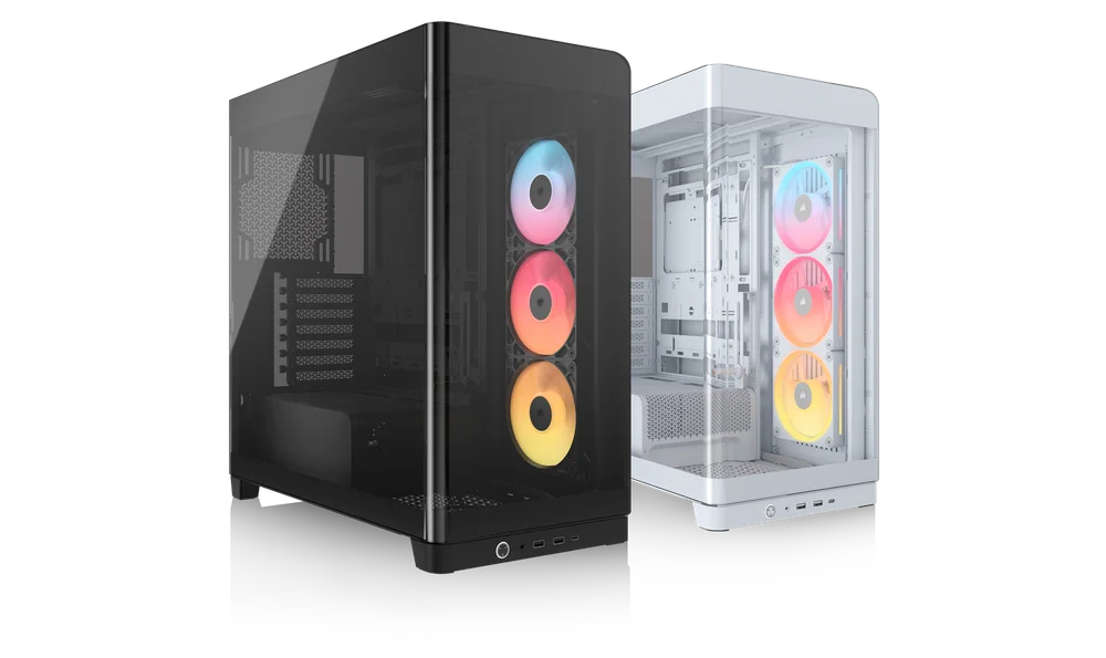
CORSAIR FRAME 4500X SERIES
TEMPERED GLASS MID-TOWER CASE
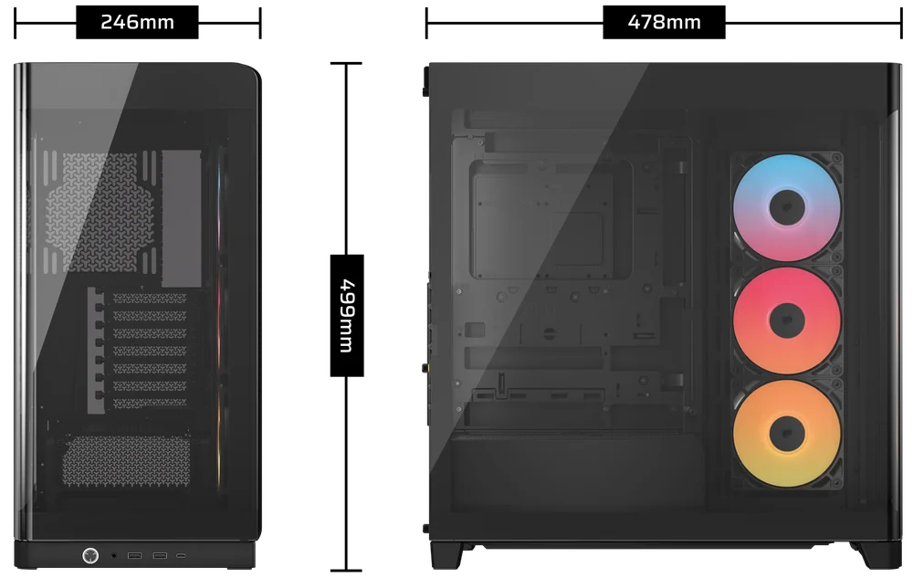
CASE SPECIFICATIONS
|
Height |
478mm |
|
Width |
246mm |
|
Length |
499mm |
|
Maximum GPU Length |
460mm |
|
Maximum CPU Cooler Height |
185mm |
|
PCI Slot Configuration |
7x Horizontal / 3x Vertical |
|
Motherboard Compatibility |
- Mini-ITX - Micro-ATX - ATX - E-ATX (305mm x 277mm) - ASUS BTF - MSI PROJECT ZERO - GIGABYTE PROJECT STEALTH |
|
Hard Disk Drives |
1x |
|
2.5" Solid State Drives |
2x |
|
Colors Available |
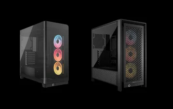
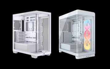
- White - Black |
|
Front and Left Side Panel Material |
Monolithic Tempered Glass with Shatter Safety Film |
|
Rear Cable Space |
34mm |
|
Dust Filters |
- Side - PSU |
|
Front I/O |
- 2x USB 3.2 Gen 1 Type-A - 1x USB 3.2 Gen 2 Type-C - 1x Power Button - 1x Combo Mic / Headphone |
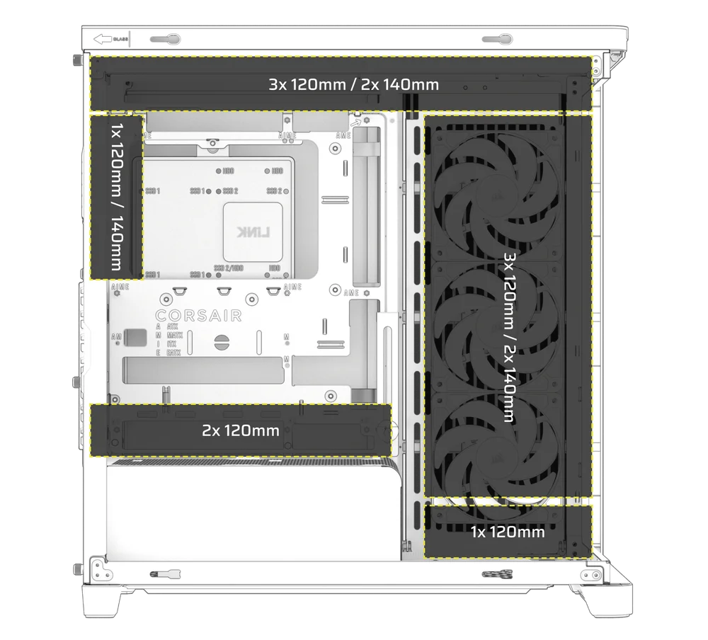
1. FAN LOCATIONS
|
Front |
Top |
Rear |
Side |
PSU Shroud |
Bottom |
|
None |
3x 120mm 2x 140mm |
1x 120mm 1x 140mm |
3x 120mm 2x 140mm |
2x 120mm |
1x 120mm |
2. INCLUDED FANS AND CONTROLLERS
|
|
FRAME 4500X RS-R ARGB |
FRAME 4500X LX-R RGB iCUE LINK |
|
Included Fans |
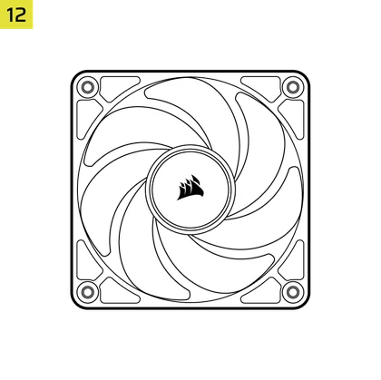
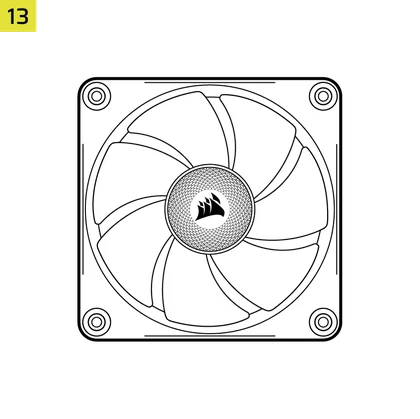
3x RS120-R (Pre-Installed) |
3x LX120-R RGB iCUE LINK (Pre-Installed) |
|
Included Fan Controllers |
None | iCUE LINK System Hub |
3. RADIATOR COMPATIBILITY
|
Front |
Top |
Rear |
Side |
PSU Shroud |
|
None |
240mm 280mm 360mm |
120mm 140mm
|
240mm 280mm 360mm |
None |
ACCESSORY KIT CONTENTS
1x Reverse Connector Magnetic Strip
1x Anti-sag Stabilization Arm Rubber Spacer
1x iCUE LINK System Hub
(FRAME 4500X LX-R RGB iCUE LINK only)
1x Front I/O Adapter
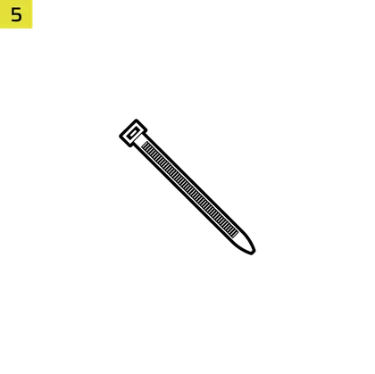
12x Zip Ties
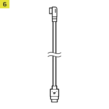
1x iCUE LINK to 90° iCUE LINK Cable
(FRAME 4500X LX-R RGB iCUE LINK only)
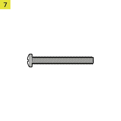
12x Long Fan Screws
(6-32 UNC)

18x Motherboard / HDD Screws
(6-32 UNC; 6mm)
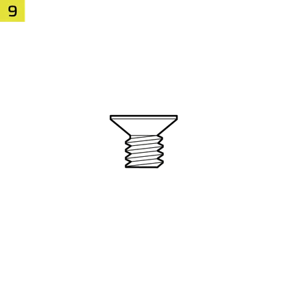
8x SSD Screws
(M3 x 0.5; 5mm)
1x Spare Motherboard Standoff

2x Vertical GPU Mount Standoffs
3x RS120-R Fans
(pre-installed on FRAME 4500X RS-R ARGB)
3x LX120-R iCUE LINK Fans
(pre-installed on FRAME 4500X LX-R RGB iCUE LINK)

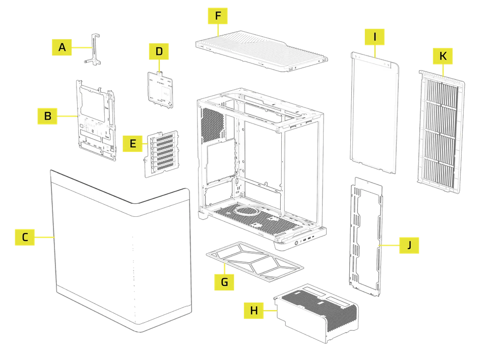
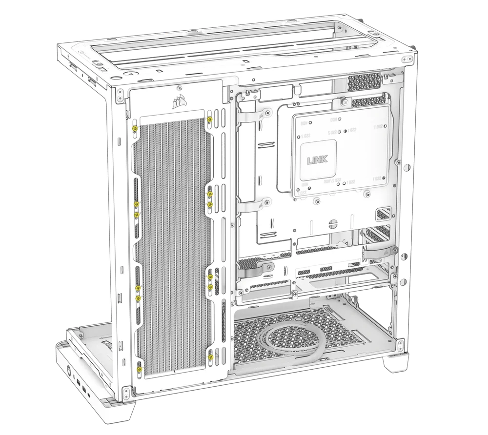
CASE EXPANDED VIEW
|
A. GPU Anti-sag Stabilization Arm
|
G. Bottom Filter |
| B. FRAME Series Steel Motherboard Tray | H. Compact PSU Shroud |
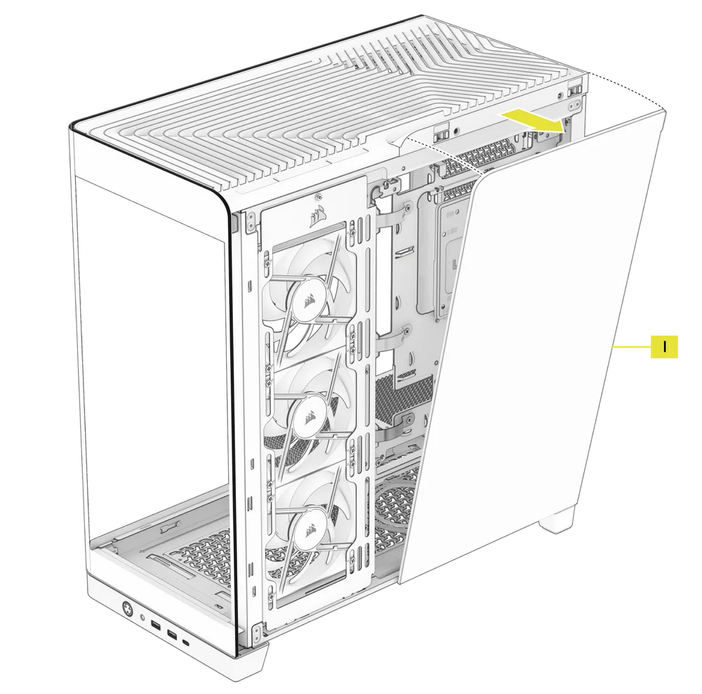
| C. Panoramic Glass Side Panel | I. Steel Side Panel |
| D. Combination Drive Plate | J. Side Fan Mount |
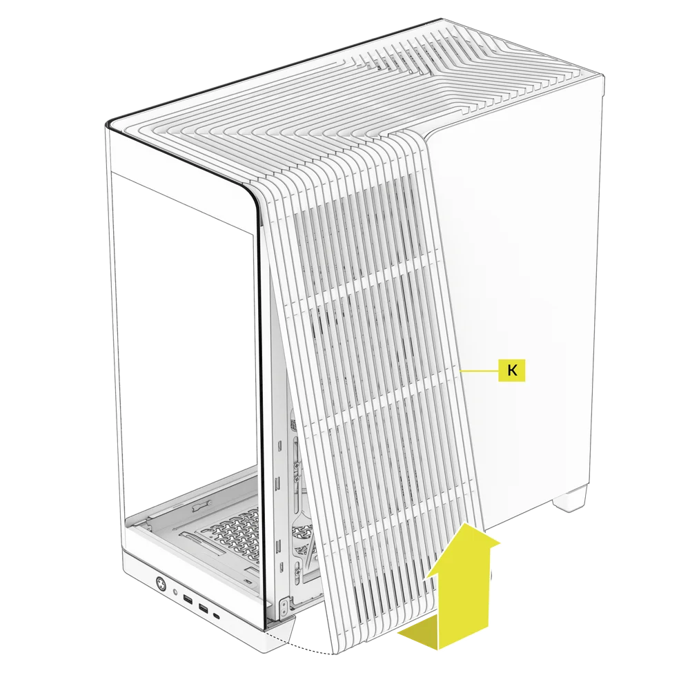
| E. PCI Plate | K. Side Panel and Filter |
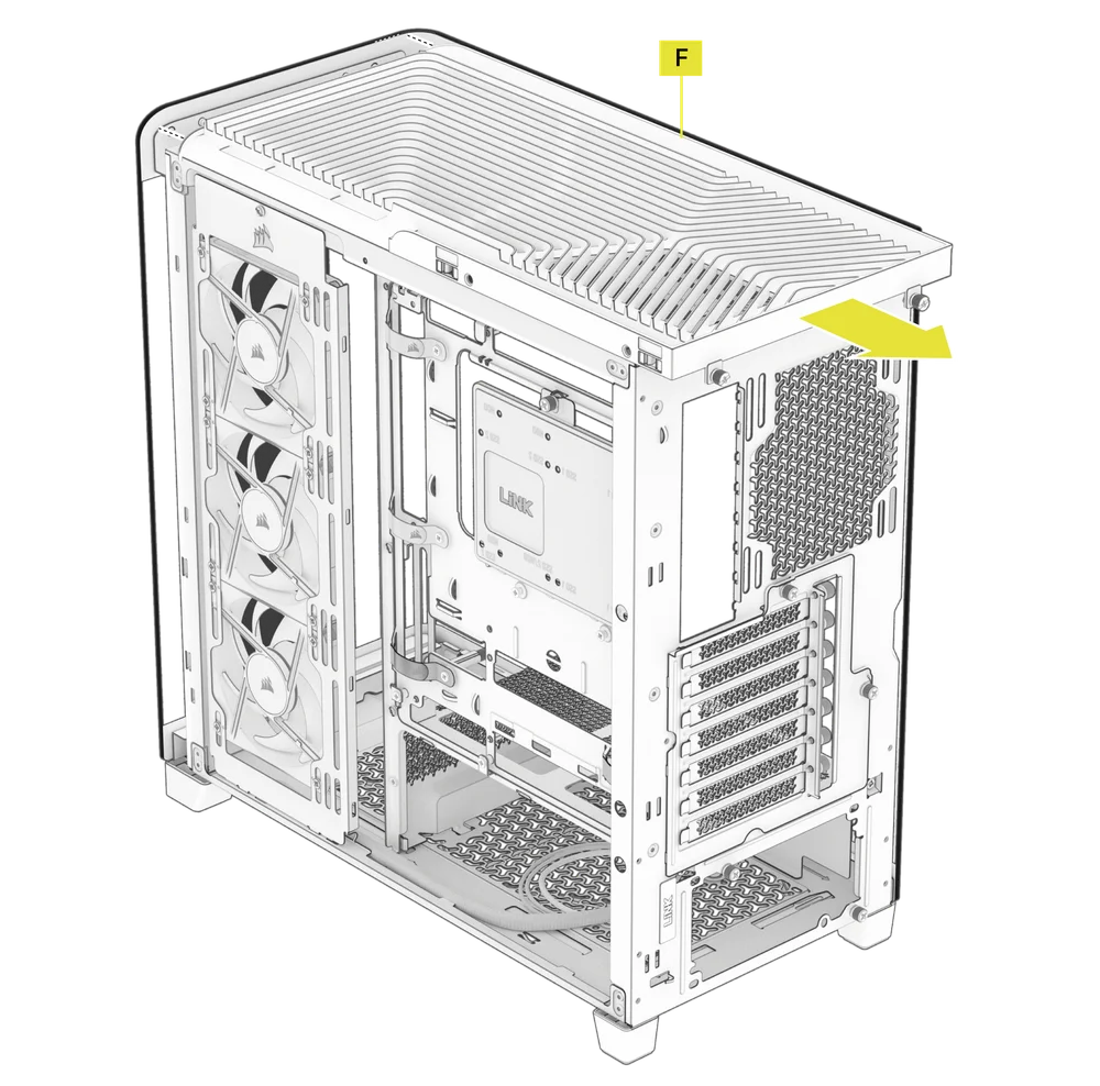
| F. Top Panel |
PANEL INSTALLATION / REMOVAL
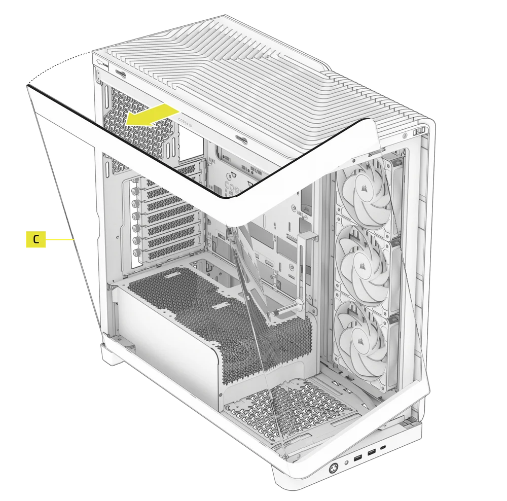
1. PANORAMIC GLASS SIDE PANEL REMOVAL
The FRAME 4500X features a single Panoramic Glass Side Panel (C), which can be removed by sliding it toward the front of the case.
- Push the Panoramic Glass Side Panel (C) from the rear of the case towards the front on the rubber pad on the glass - the panel should slide forward.
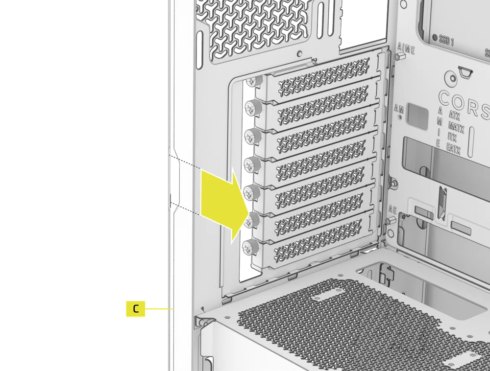
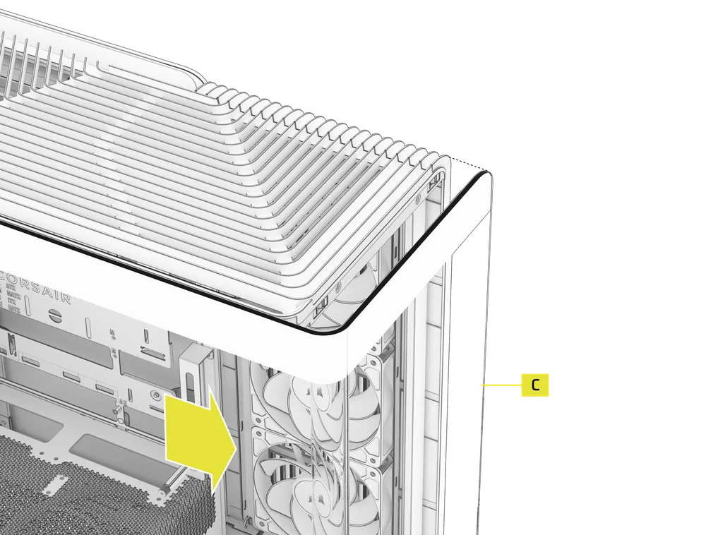
- Tip the Panoramic Glass Side Panel (C) to the left and raise it off the case chassis.
2. SIDE PANEL AND FILTER REMOVAL
- Remove the Side Panel and Filter (K) by pulling it upward from the bottom.
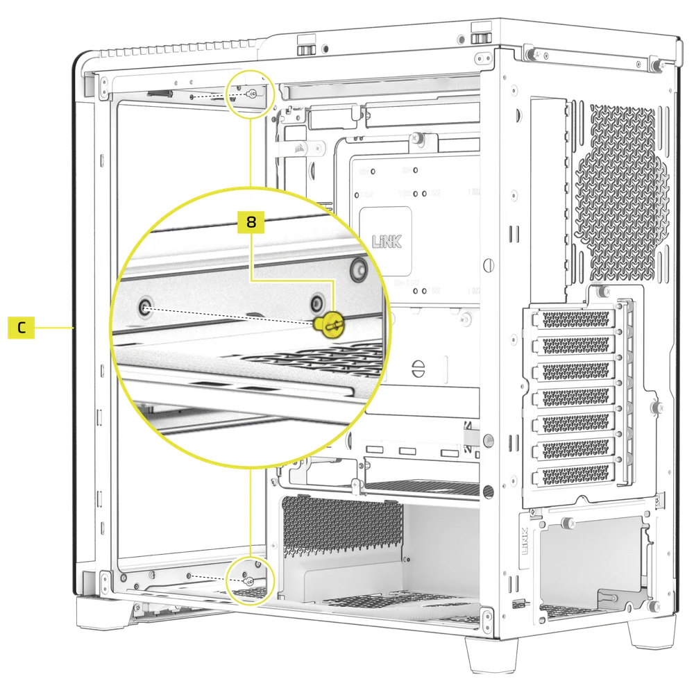
3. STEEL SIDE PANEL REMOVAL
- Remove the Steel Side Panel (I) by tipping it off the back of the case.
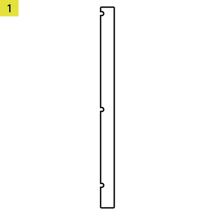
4. TOP PANEL REMOVAL
- Unscrew the two captive thumbscrews in the rear and gently slide the top cover towards the rear to remove the Top Panel (F).
5. PSU SHROUD REMOVAL
The Compact PSU Shroud (H) is secured with three screws - two in the rear of the case and one along the motherboard tray.
- Remove two screws in the rear of the case.
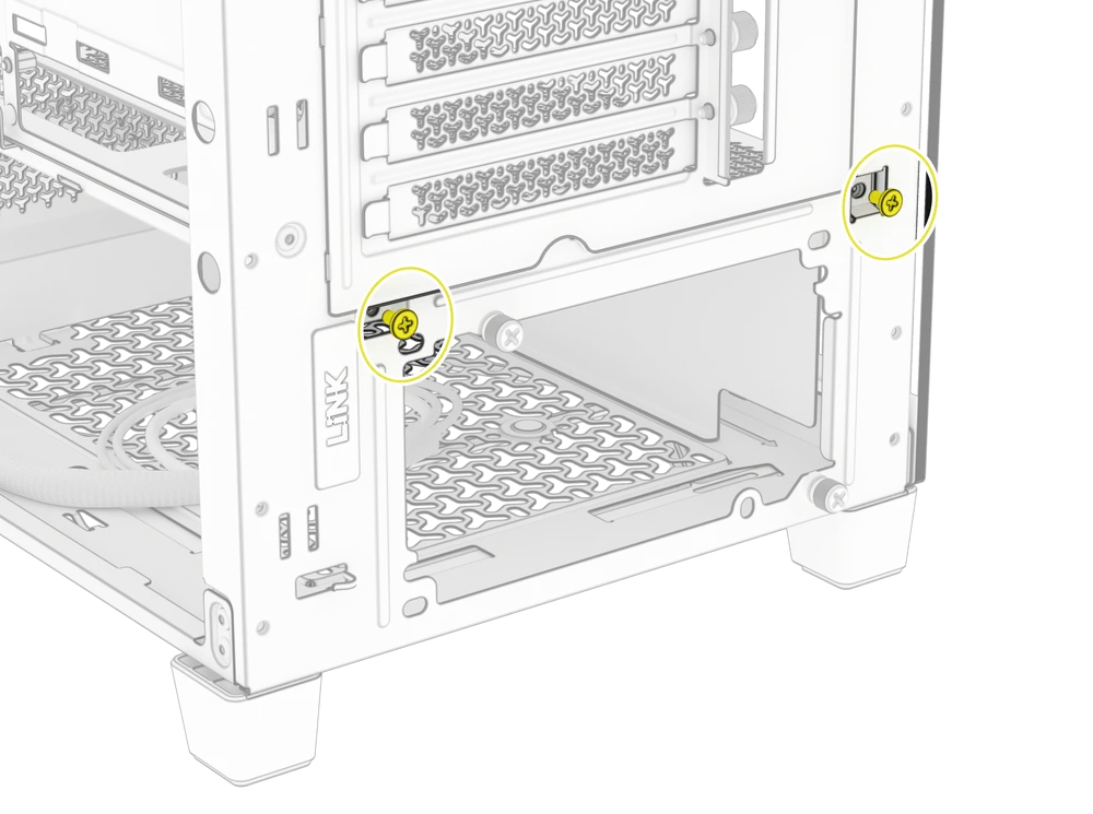
- Remove the screw along the motherboard tray.
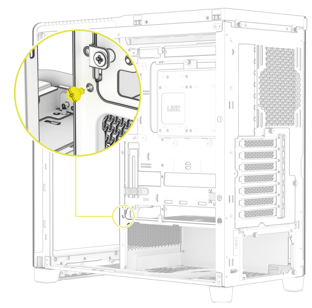
- Remove the Compact PSU Shroud (H) from the case.
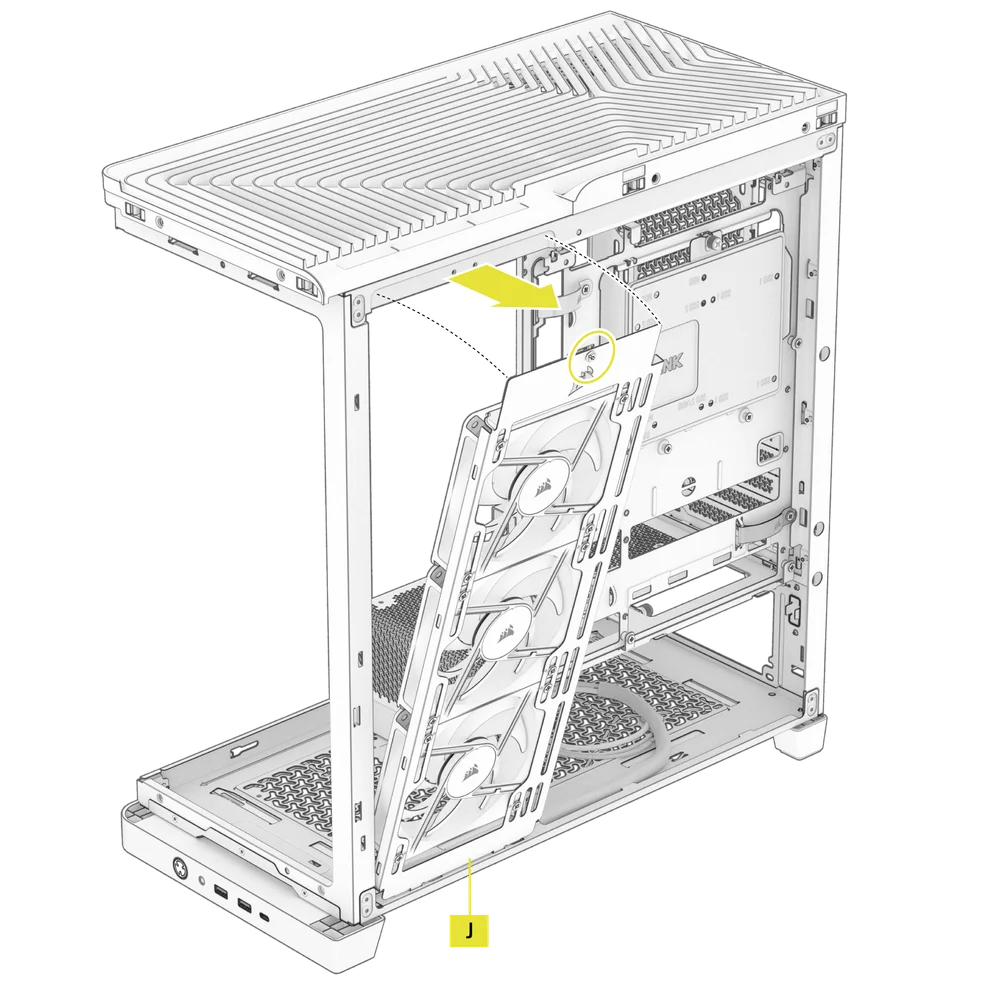
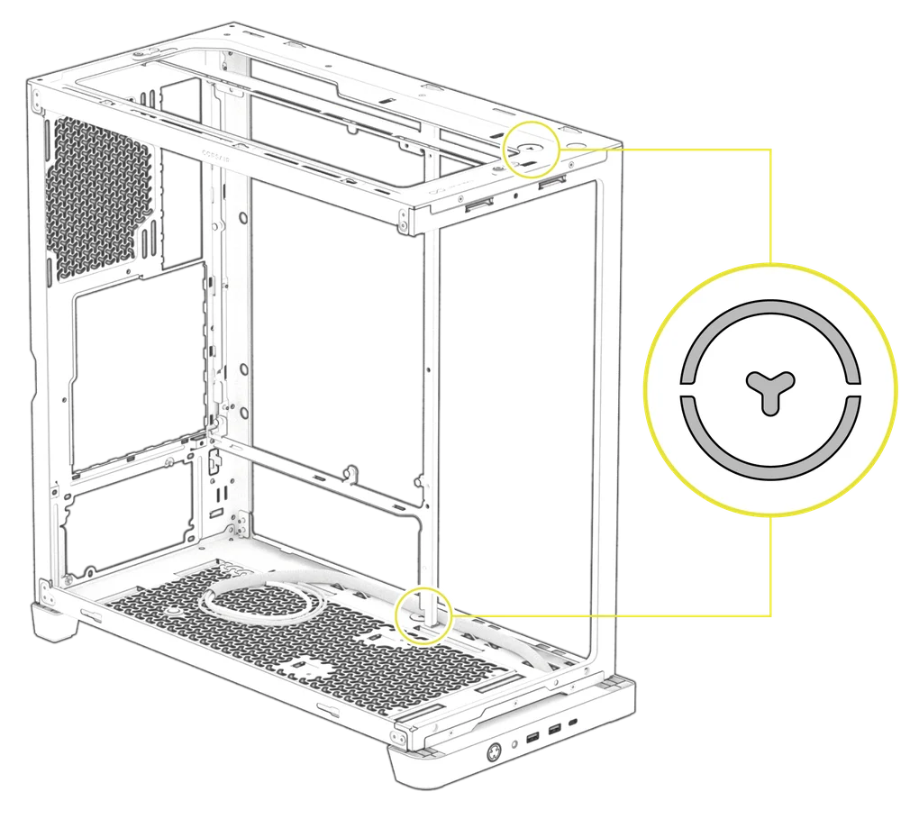
6. SIDE FAN MOUNT REMOVAL
The FRAME 4500X comes with a Side Fan Mount (J) that includes pre-installed intake fans, but it is removable if you wanted to clean the fans or swap them out.
- Remove the single screw on the top and tilt the Side Fan Mount (J) out to detach it.
- To install the Side Fan Mount (J), align the bottom notches of the mount with the corresponding holes at the bottom of the case, and secure it using the top screw.
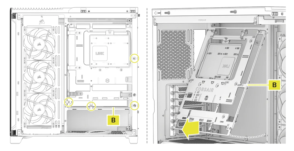
7. MOTHERBOARD TRAY REMOVAL
The FRAME Series Steel Motherboard Tray (B) is secured with four screws located along its back edge.
- Remove the four screws in the back of the FRAME Series Steel Motherboard Tray (B).
- Tilt the bottom part of the tray outward to remove it.
MOTHERBOARD INSTALLATION
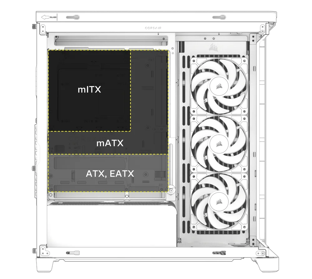
The FRAME 4500X supports mITX, mATX, ATX, E-ATX motherboards, and ASUS BTF, MSI Project Zero, and GIGABYTE Project STEALTH motherboards with reverse connectors.
- Align your motherboard with the standoffs and secure it using the Motherboard Screws (8).
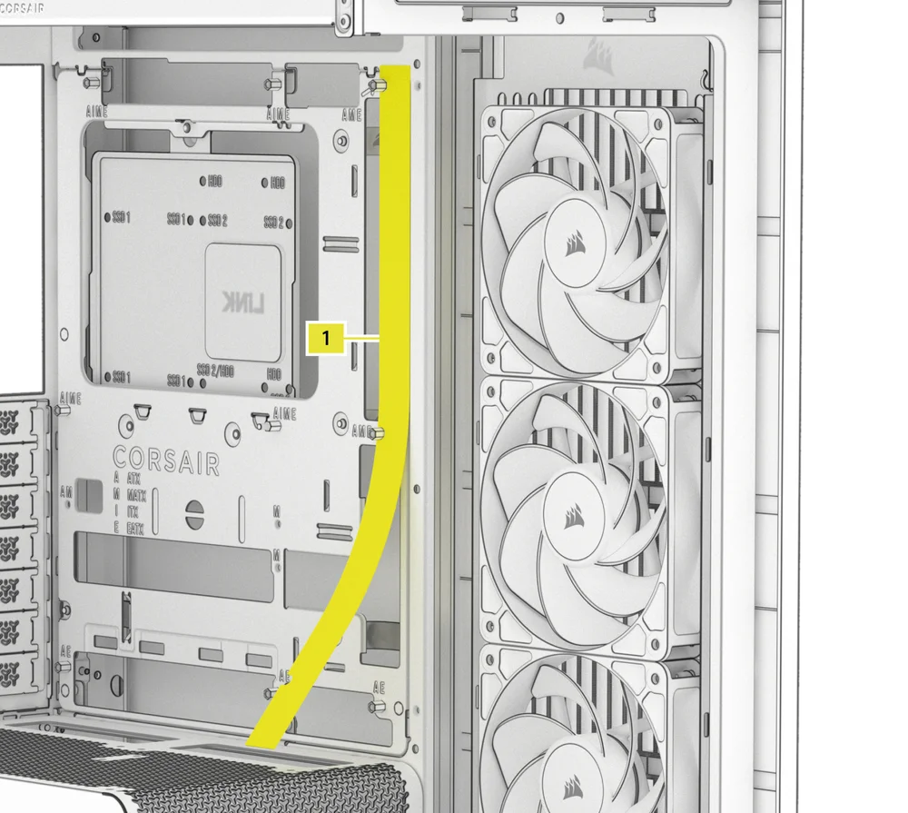
MAGNETIC STRIP INSTALLATION
The FRAME 4500X includes a Reverse Connector Magnetic Strip (1), designed to cover the exposed edge of the reverse connector holes in the motherboard tray.
- Align the Reverse Connector Magnetic Strip (1) to your standoffs and adjust side to side to close the gap on your motherboard.
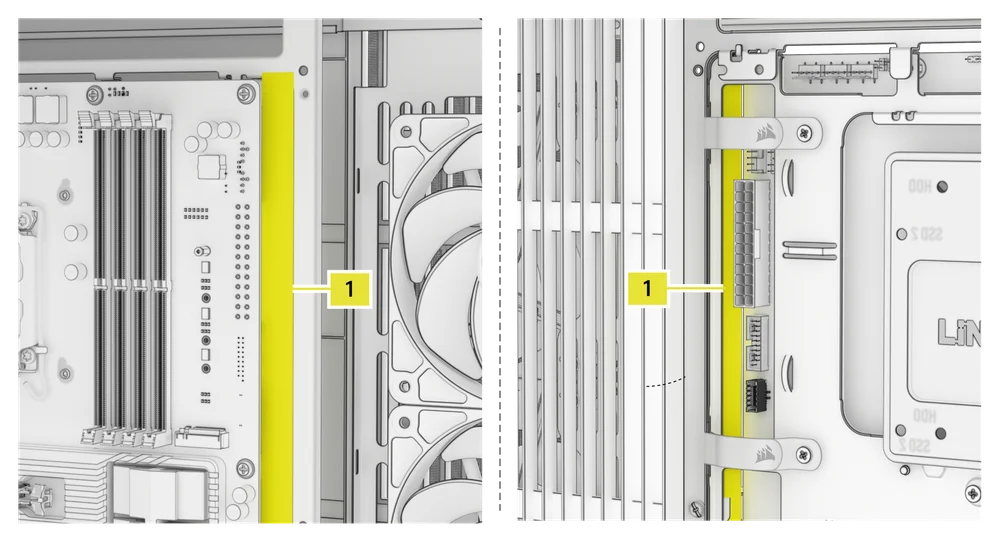
1. MOTHERBOARD WITH REVERSE CONNECTORS
If you're installing a motherboard with reverse connector compatibility, the Reverse Connector Magnetic Strip (1) can be used to fill the gap around the 24-pin ATX port, providing a cleaner and more polished appearance.
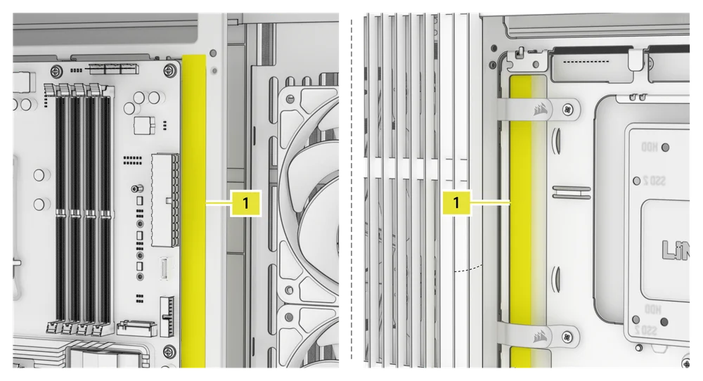
2. MOTHERBOARD WITH STANDARD CONNECTORS
When installing a standard motherboard, you can slide the Reverse Connector Magnetic Strip (1) behind the board, aligning it with the screw holes along the motherboard tray, to cover the reverse connector slot and conceal any wires running along the motherboard tray for a cleaner look.
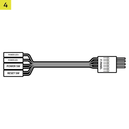
FRONT PANEL I/O CABLES INSTALLATION
1. STANDARD INTEL MOTHERBOARDS
- Connect the FPANEL plug to the front panel I/O header on your motherboard, aligning it with the keyed layout. This header is often labeled JFP1 on some motherboards.
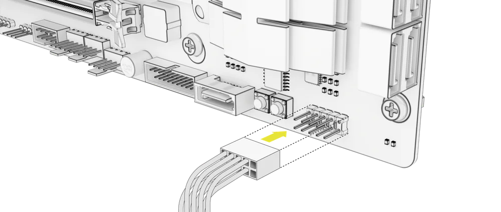
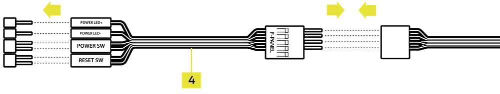
2. AMD OR NON-STANDARD INTEL MOTHERBOARDS
- Use the included Front I/O Adapter (4) to connect the FPANEL plug to the individual front panel header pins.
3. FRONT I/O EXPLANATION
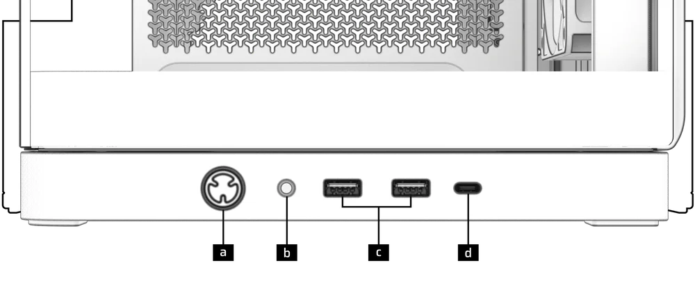
| a) Power Button | c) 2x USB 3.2 Gen 1 Type-A ports |
| b) Headphone / Mic Combination Jack | d) 1x USB 3.2 Gen 2 Type-C port |
4. FRONT I/O CONNECTIONS
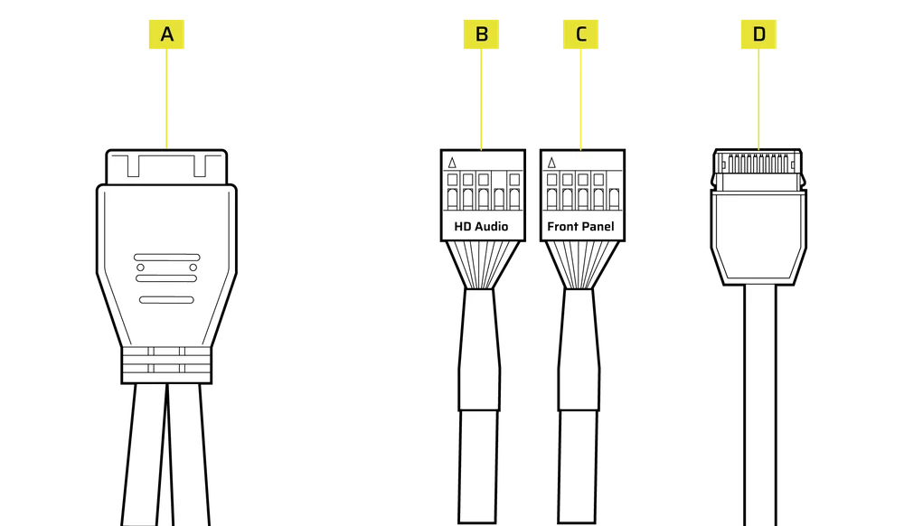
| A. USB 3.2 Gen 1 Type-A | C. Front Panel (Power LED, Power Button) |
| B. HD Audio | D. USB 3.2 Gen 2 Type-C |
FAN INSTALLATION
The FRAME 4500X can mount up to 10x 120mm or 5x 140mm fans on the top, side, rear, PSU shroud, and bottom of the case.
|
Front |
Top |
Rear |
Side |
PSU Shroud |
Bottom |
|
None |
3x 120mm 2x 140mm |
1x 120mm 1x 140mm |
3x 120mm 2x 140mm |
2x 120mm |
1x 120mm |
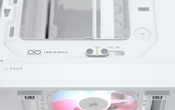
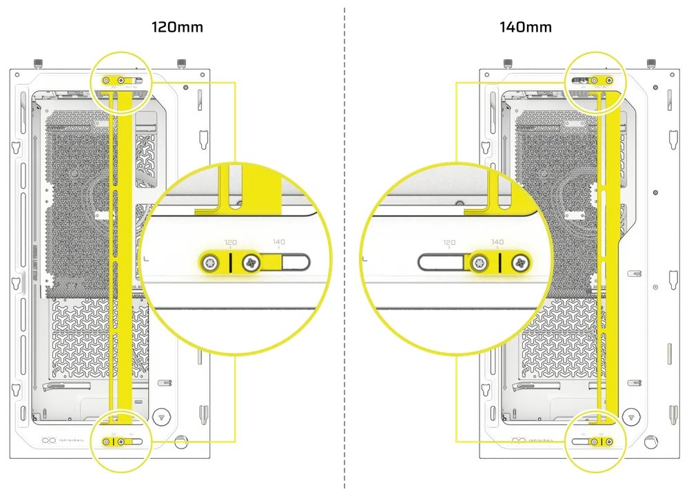
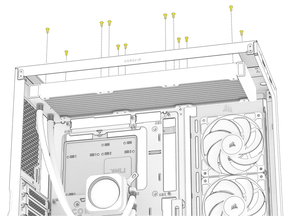
USING THE INFINIRAIL™ FAN MOUNTING SYSTEM
CORSAIR's InfiniRail is an innovative fan and radiator mounting system designed to offer exceptional flexibility and ease of use in PC case builds. Unlike traditional cases with fixed mounting points, InfiniRail utilizes adjustable steel rails that allow users to slide and position fans and radiators precisely where needed.
The FRAME 4500X features the InfiniRail system on the top of the case.
- Loosen the Philips head screw on both ends of the InfiniRail to adjust fan size from 120mm to 140mm.
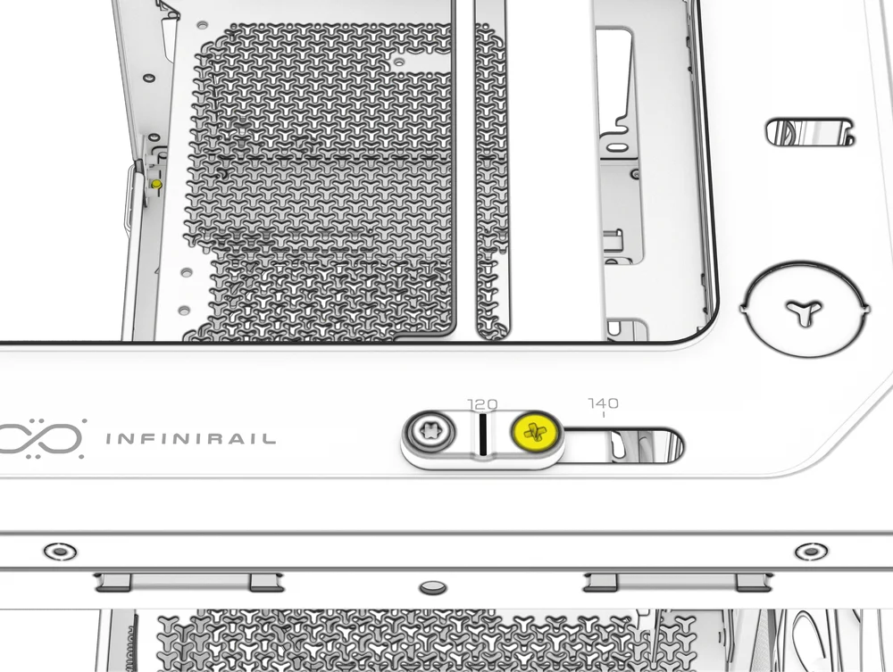
- Tighten the Philips set screws on the top and bottom of the InfiniRail to secure your mounting location.
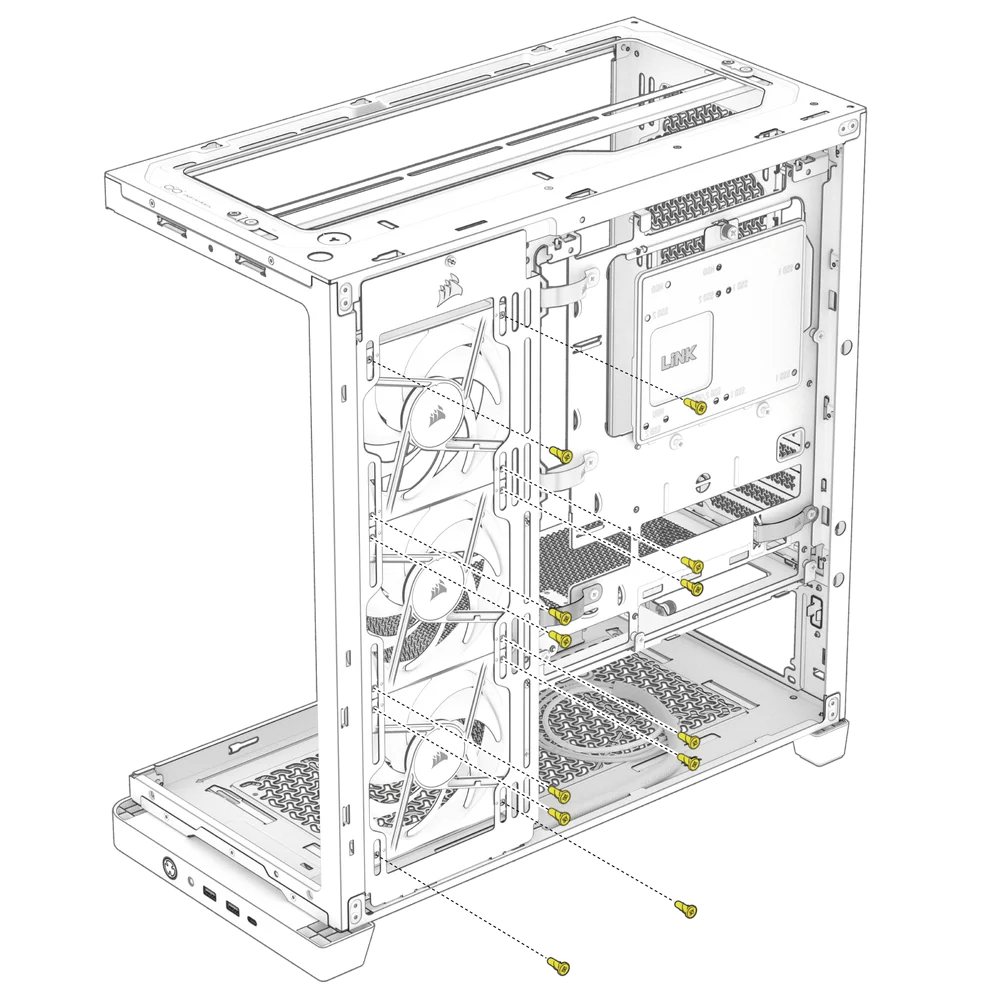
2. INSTALLING FANS ON THE TOP
- Align your fans to the InfiniRail fan mounting slots and and secure them with screws provided by the fan manufacturer.

3. INSTALLING FANS ON THE SIDE
To install fans on the side, ensure you have the Side Fan Mounting Bracket (J) installed.
- Align your fans to the fan mounting slots, and and secure them by screwing standard self-tapping fan screws into the fan frame.
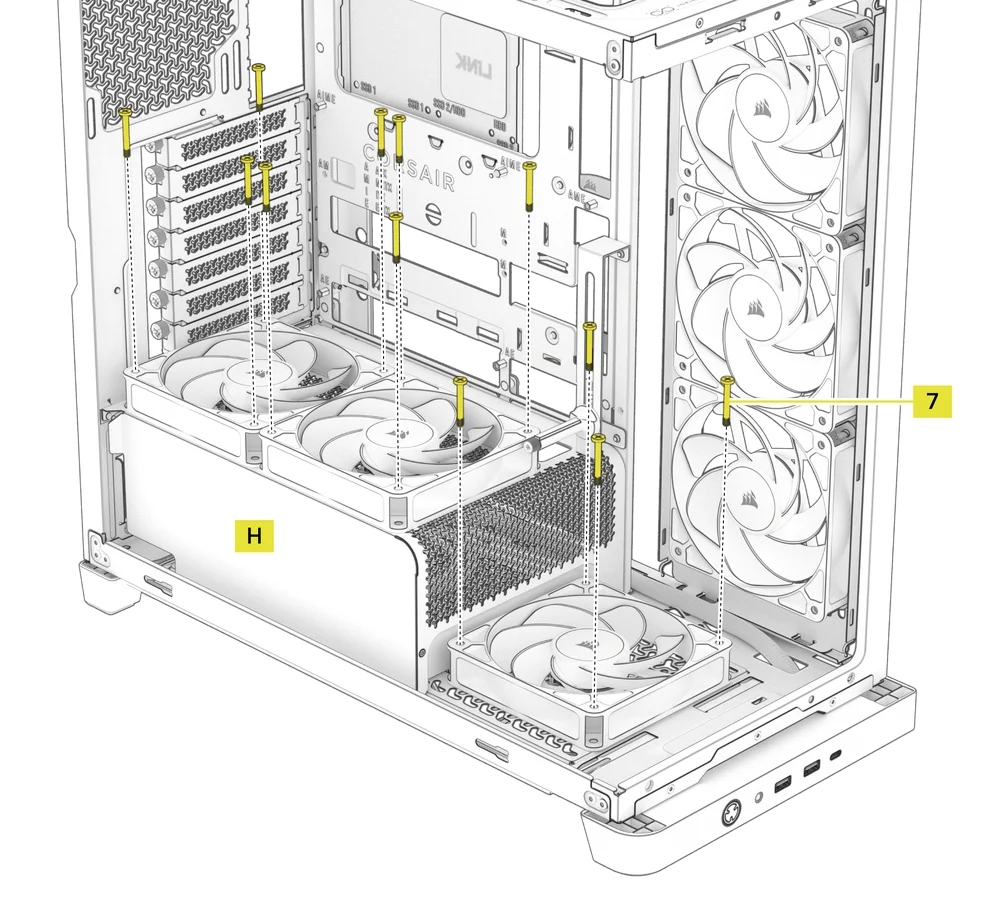
4. INSTALLING FANS ON THE BOTTOM AND THE PSU SHROUD
- Align your fans to the fan mounting holes on the bottom of the case and on the PSU Shroud (H).
- Secure the fans with Long Fan Screws (7).
HYDRO X CUSTOM COOLING SUPPORT
The FRAME 4500X has fill / drain ports pre-punched in the top and bottom panels for a Hydro X open loop liquid cooling setup.
- Remove the port covers by gently prying them off with a flathead screwdriver.
RADIATOR INSTALLATION
The FRAME 4500X offers several locations to mount a radiator for liquid cooling, with the top location featuring an adjustable InfiniRail fan mount. Please refer to the Fan Installation section for details on using the InfiniRail Fan Mounting System.
|
Front |
Top |
Rear |
Side |
PSU Shroud |
|
None |
240mm 280mm 360mm |
120mm 140mm
|
240mm 280mm 360mm |
None |
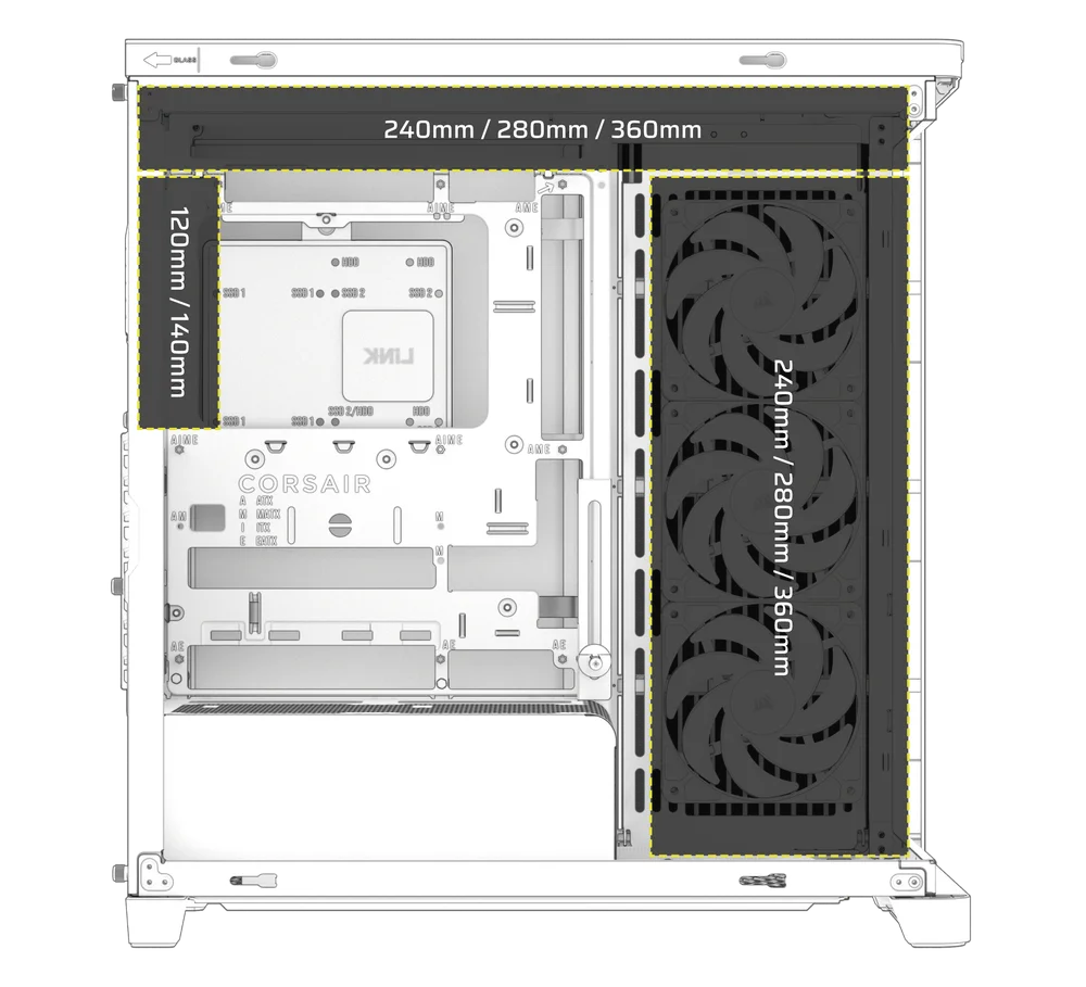
Top mounting provides optimal noise performance, but other mounts can be utilized based on your build preferences. Consult your cooler's product manual for more tips on usage and best practices.
With the appropriate mounting screws, radiators can be securely installed on the side of the case as well.
INSTALLATION OF STORAGE DEVICES AND CONTROLLERS
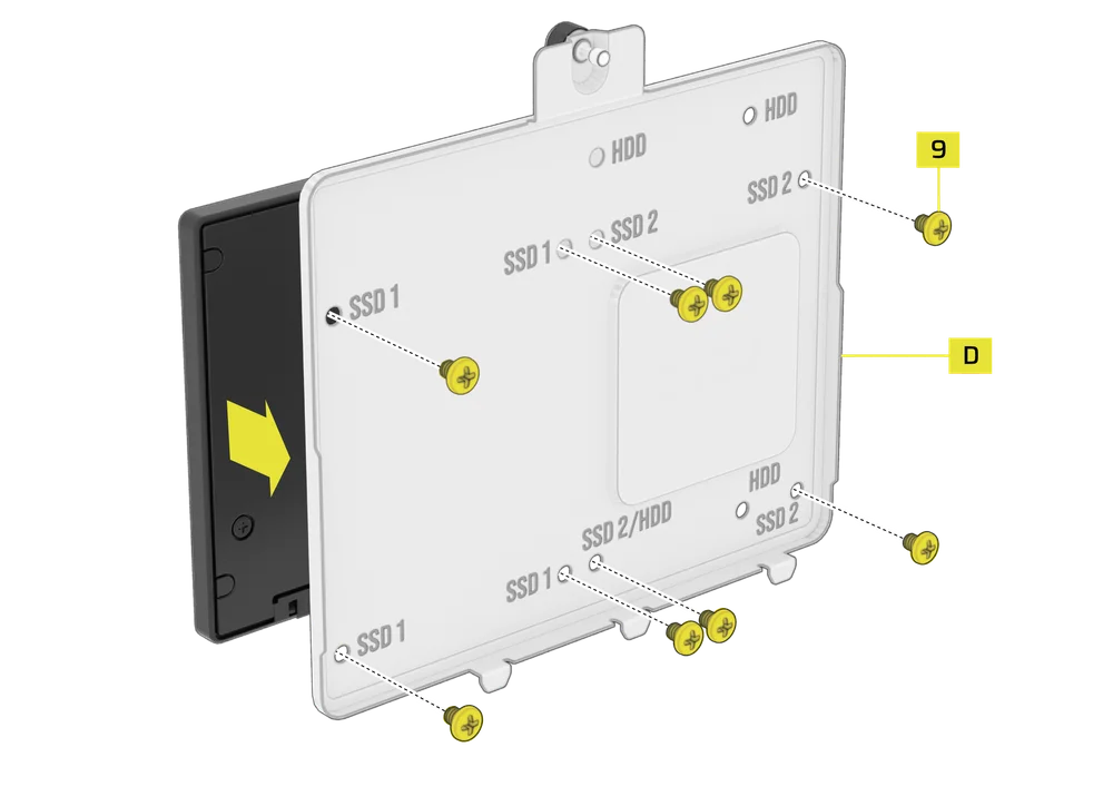
The FRAME 4500X Series includes one Combination Drive Plate (D), that allows you to mount a single 3.5" HDD or two 2.5" SSDs.
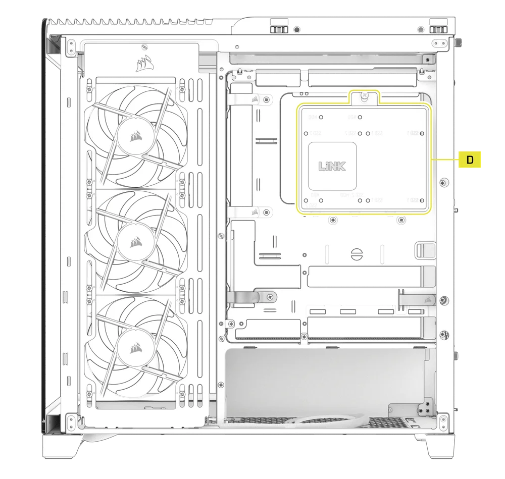
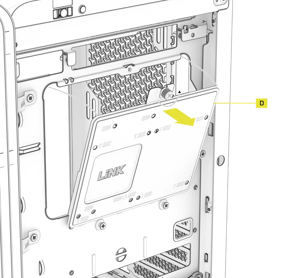
1. COMBINATION DRIVE PLATE REMOVAL
- To remove the Combination Drive Plate (D), unscrew the single captive thumbscrew and remove the plate.
2. HDD INSTALLATION ON THE COMBINATION DRIVE PLATE
- Install the HDD onto the bottom of the Combination Drive Plate (D) by securing it using the included HDD Screws (8) found in the accessory box.
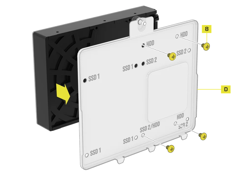
3. SSD INSTALLATION ON THE COMBINATION DRIVE PLATE
- Install an SSD onto the bottom of the Combination Drive Plate (D) by securing it using the included SSD Screws (9) found in the accessory box.
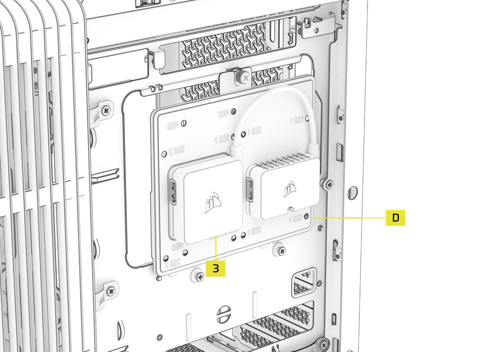
3. iCUE LINK SYSTEM HUB INSTALLATION ON THE COMBINATION DRIVE PLATE
The Combination Drive Plate (D) also serves as a mounting location for an iCUE LINK System Hub (3), if one is used.
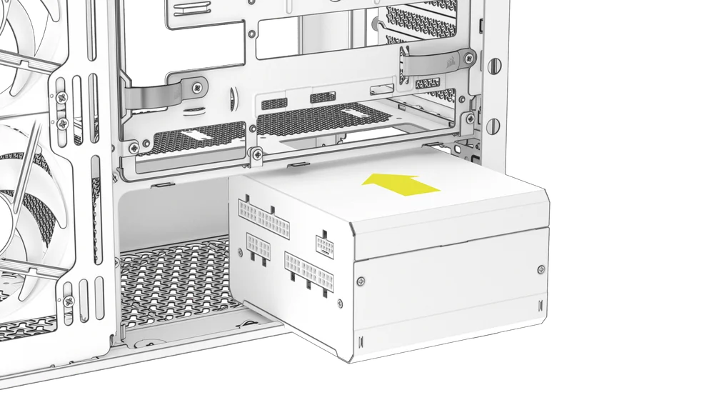
POWER SUPPLY INSTALLATION
1. STANDARD POWER SUPPLY INSTALLATION
- Install the PSU with the fan facing down.
- Secure the power supply to the chassis with the two captive screws located on the back of the FRAME 4500X.
- For additional security, secure the PSU using two Motherboard Screws (8) screws in the corners of the rear panel.
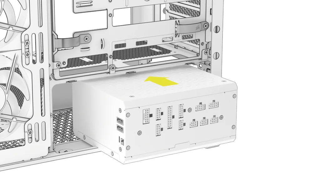
2. CORSAIR SHIFT POWER SUPPLY INSTALLATION
The FRAME 4500X is fully compatible with CORSAIR SHIFT power supplies and installs identically to a standard ATX PSU.
- Install the PSU with the fan facing down.
- Secure the two captive screws to the PSU exhaust area.
- For additional security, secure the PSU using two Motherboard (8) screws in the corners of the rear panel.
GRAPHICS CARD INSTALLATION
The included PCI bracket allows the FRAME 4500X to support both horizontal and vertical GPU mounting configurations.
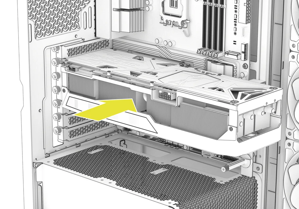
1. INSTALLING A GPU IN A STANDARD ORIENTATION
- Remove thumbscrews and PCIe slot covers.
- Insert the card into the PCIe slot until it clicks into place with the PCIe slot's retention retention mechanism.
- Align the bracket with the PCIe slots and secure the card to the case.
2. INSTALLING A GPU IN A VERTICAL ORIENTATION
The FRAME 4500X supports vertical GPU mounting with the included PCI plate and a PCIe Riser Card (sold separately).
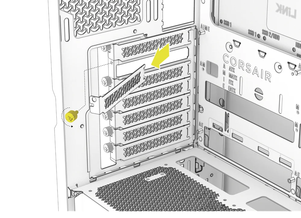
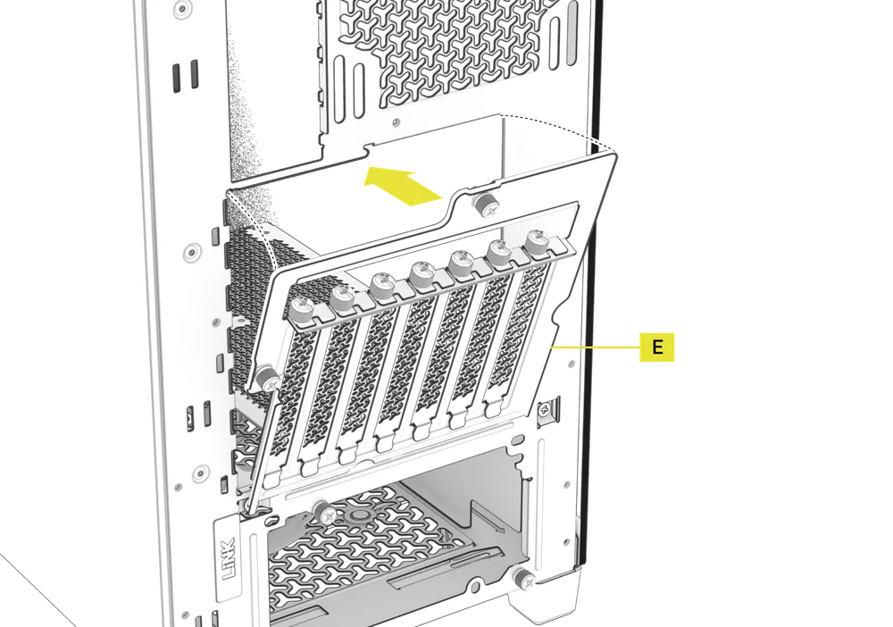
- Uninstall the PCI Plate (E) by loosening the two captive screws at the rear of the case.
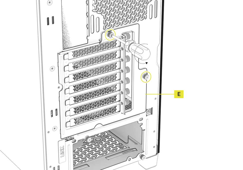
- Rotate the PCI Plate (E) 90 degrees counterclockwise so that the PCIe slot cover thumbscrews face upward.
- Re-screw the two previously removed thumbscrews.
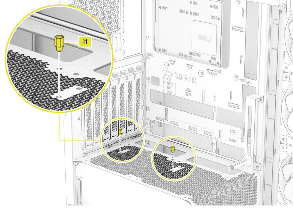
- Install the Vertical Mount Standoffs (11) from the accessory box to the top of the PSU shroud. There are two locations for standoffs, so choose the location that best suits the size of your GPU in relation to how far it is from the side panel.
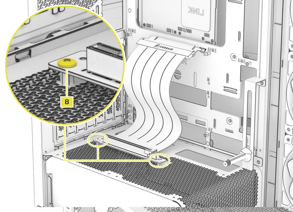
- Mount the PCIe Riser Card (sold separately) to the standoffs using two of the included Motherboard Screws (8).
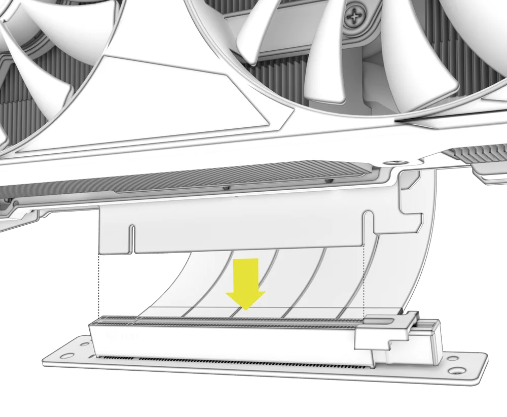
- Mount the GPU into the PCI bracket by firmly seating it into the riser card until it clicks, then secure it to the PCI plate with a thumbscrew.
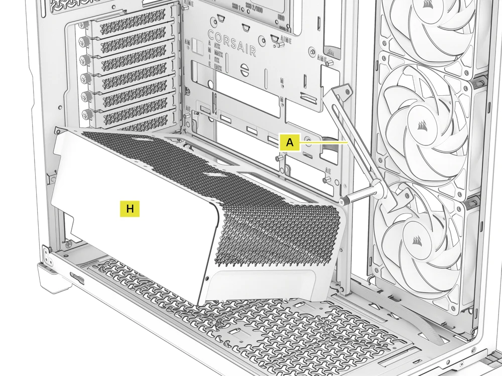
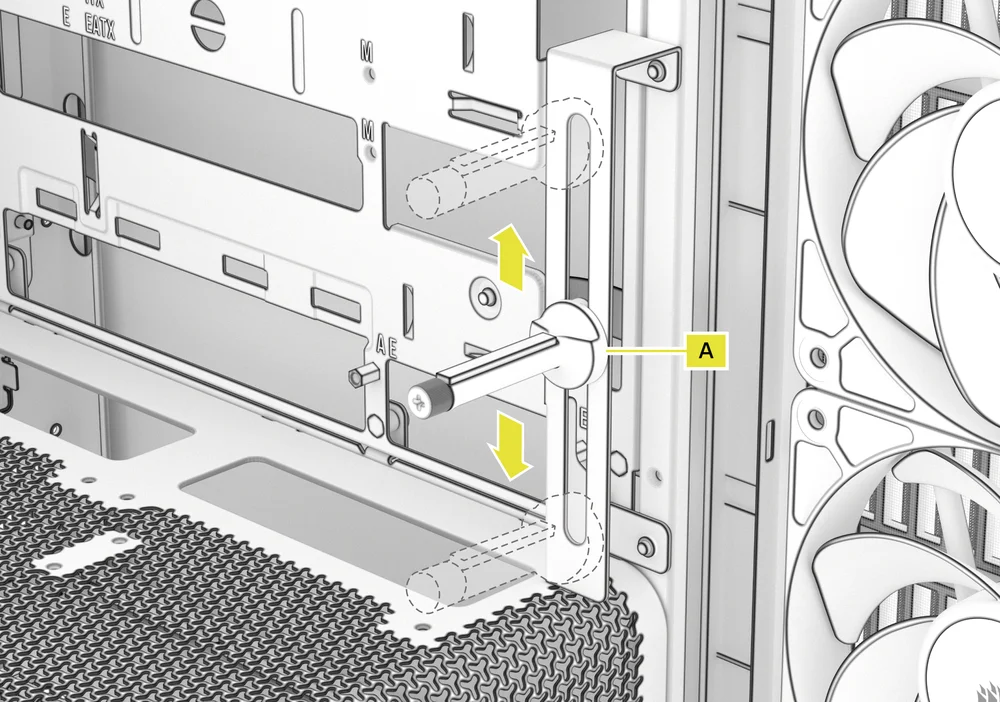
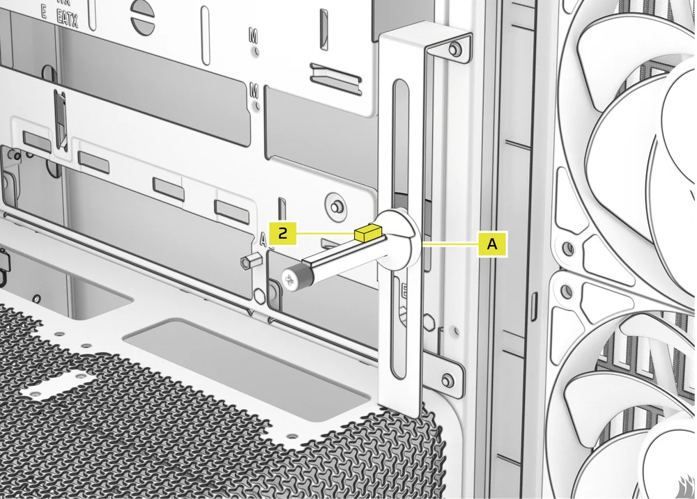
3. USING THE GPU ANTI-SAG STABILIZATION ARM
The GPU Anti-sag Stabilization Arm supports your graphics card, preventing it from bending or sagging under the weight of its heatsink. This not only helps protect your graphics card and PCIe slot, but also contributes to a cleaner, more professional-looking build.
- Adjust the GPU Anti-sag Stabilization Arm (A) by loosening the front-facing thumbscrew and sliding the arm up or down until it properly supports your graphics card.
If your GPU fan or other parts come into contact with the rubber arm, use the included Anti-sag Stabilization Arm Rubber Spacer (2) from the accessory box to ensure clearance from any moving parts.
- Attach the self-adhesive Anti-sag Stabilization Arm Rubber Spacer (2) to the GPU Anti-sag Stabilization Arm (A).
CONNECTING YOUR FANS
1. CONNECTING AND CONTROLLING FANS FOR FRAME 4500X RS-R ARGB
Please visit the CORSAIR RS120-R ARGB Quickstart Guide to complete the fan connection.
2. CONNECTING AND CONTROLLING FANS FOR FRAME 4500X LX-R RGB iCUE LINK
Please visit the CORSAIR iCUE LINK LX-R RGB Quickstart Guide to complete the fan connection.
MAINTENANCE
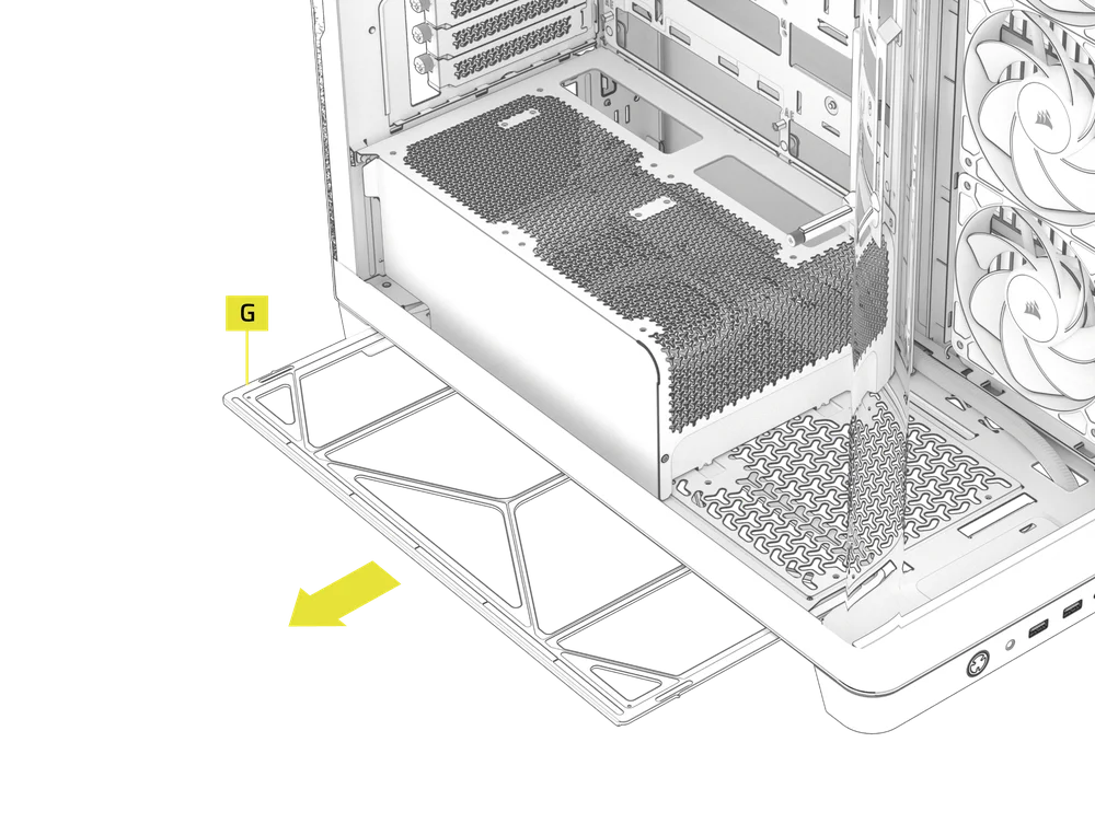
1. CLEANING YOUR CASE FILTERS
The FRAME 4500X includes two removable dust filters - a Bottom Filter (G) and a Side Filter (K). Filters can be cleaned with pressurized air or water. If you rinse your filter, ensure filters are fully dry before reinstalling.
- To remove the Side Filter and Panel (K), pull the panel up from the bottom.
- To remove the Bottom Filter (G), slide the filter away from the left side of the case.
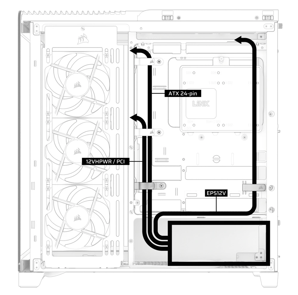
2. CABLE MANAGEMENT TIPS
- Use the built-in cable management features to keep your cables tamed and out of the way of your PC’s airflow.
- Zip tie points are strategically placed for routing power cables to specific devices.
- LINK cable hooks in the top panel to securely hold LINK cables without permanent attachment.
- This case supports most reverse connector motherboards (MSI, ASUS, GIGABYTE) that feature connectors on the rear face of the board to provide you with the cleanest possible build.
- A dedicated location for your iCUE LINK System Hub keeps your controller from moving around and looks tidy.
SPARE PARTS LISTING
| CC-8901050 |
FRAME 4500X Replacement Glass Panel, Front/Left, Black
|
| CC-8901051 |
FRAME 4500X Replacement Glass Panel, Front/Left, White
|
| CC-8901052 |
FRAME 4500X Replacement Top Panel Assembly, Black
|
| CC-8901053 |
FRAME 4500X Replacement Top Panel Assembly, White
|
| CC-8901054 |
FRAME 4500X Side Grill, Black
|
| CC-8901055 |
FRAME 4500X Side Grill, White
|
| CC-8901056 |
FRAME 4500X Replacement Steel (Right) Side Panel, Black
|
| CC-8901057 |
FRAME 4500X Replacement Steel (Right) Side Panel, White
|
| CC-8901058 |
FRAME 4500X Replacement I/O and Front Foot, Black
|
| CC-8901059 |
FRAME 4500X Replacement I/O and Front Foot, White
|
| CC-8901060 |
FRAME 4500X Rear Foot, Black
|
| CC-8901061 |
FRAME 4500X Rear Foot, White
|
| CC-8901062 |
FRAME 4500X Replacement Accessory Box, Black
|
| CC-8901063 |
FRAME 4500X Replacement Accessory Box, White
|
| CC-8901064 |
FRAME 4500X Replacement Ball Snaps, Black
|
| CC-8901065 |
FRAME 4500X Replacement Ball Snaps, White
|
| CC-8900931 |
FRAME 4000D/4500X Replacement PCI Bracket, Black
|
| CC-8900932 |
FRAME 4000D/4500X Replacement PCI Bracket, White
|
| CC-8900933 |
FRAME 4000D/4500X Replacement Top InfiniRail, Black
|
| CC-8900934 |
FRAME 4000D/4500X Replacement Top InfiniRail, White
|
| CC-8900939 |
FRAME 4000D/4500X Replacement Drive/Controller Plate, Black
|
| CC-8900940 |
FRAME 4000D/4500X Replacement Drive/Controller Plate, White
|
| CC-8900945 |
FRAME 4000D/4500X Replacement Strap Kit, Black
|
| CC-8900946 |
FRAME 4000D/4500X Replacement Strap Kit, White
|
| CC-8900953 |
FRAME 4000D/4500X Series GPU Anti-sag Stabilization Assembly, Black
|
| CC-8900954 |
FRAME 4000D/4500X Series GPU Anti-sag Stabilization Assembly, White
|
| CC-8900966 |
FRAME Motherboard, Standard (4000D/4500X) Steel ATX, Black
|
| CC-8900967 |
FRAME Motherboard, Standard (4000D/4500X) Steel ATX, White
|
| CC-8901097 |
CORSAIR RS120-R ARGB, 120mm ARGB Fan, Single Pack
|
| CC-8901098 |
CORSAIR RS120-R ARGB White, 120mm ARGB Fan, Single Pack
|
| CO-8950034 |
RS/RS ARGB PWM Extension Cable 3-pack, Black
|
| CO-8950035 |
RS/RS ARGB PWM Extension Cable 3-pack, White
|
| CO-9051049-WW |
LX120-R RGB iCUE LINK 120mm PWM Reverse Fan Expansion
|
| CO-9051053-WW |
LX120-R RGB iCUE LINK 120mm PWM Reverse Fan Expansion, White
|
WARRANTY

CORSAIR FRAME 4500X Series computer cases come with a 2-year warranty.
LEGAL
© 2025 CORSAIR MEMORY, Inc. All rights reserved. InfiniRail, CORSAIR and the sails logo are registered trademarks of CORSAIR in the United States and/or other countries. All other trademarks are the property of their respective owners. Product may vary slightly from those pictured.
RELATED CONTENT