快速入門指南
平台系列
組合式電腦桌

開始之前
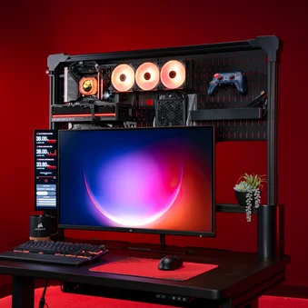
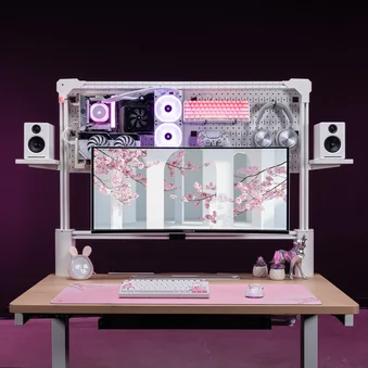
恭喜您購買全新的 CORSAIR 平台系列辦公桌。
請在組裝前花點時間仔細閱讀本指南。
平台系列辦公桌 - 配件清單
大型清單
*不適用於 Platform:4
** 某些機型需另行購買

桌面 (1x)

T 型通道軌道 (1x)

腳 (2x)

左右腳 (各 1x)

D 型托架 (2x)

電線管理托盤 (1x)

橫梁支撐桿 (1x)

左右邊角支撐 (各 1x)

3 埠電源插座 (1x)

Cubby 模組 (1x)
(預先安裝於 Platform:6)

小物品清單
*不適用於 Platform:4
** 某些機型需另行購買
*** 僅限 Elevate 機型

M4 15mm 螺栓 (2x)

M6 10mm 螺栓 (8x)

M6 15mm 螺栓 (10x)

M8 15mm 螺栓 (16x)

M6 黑色 T 型螺帽 (10x)

1/4" 20 銀色 T 型螺帽 (6x)

翼型螺帽螺絲 (2x)
棘輪螺栓 (2x)

電源線滑軌安裝 (1x)

桌上型電源插座 (1x)

控制器 (1x)

直線電纜通道 (2x)

彎曲電纜通道 (2x)

電源供應器 (1x)

小型電線管理托盤 (2x)
(1x 搭配平台:4)

Elgato 軟臂轉接器 (1x)
Elgato 多重安裝轉接器 (2x)

支撐桿外罩 (2x)

木榫 (4x)

電源線 (1x)

搭扣粘扣帶 (10x)
黏扣帶 (10x)

棘輪扳手和 5mm 六角銼刀 (1x)

3mm 六角工具 (1x)

5mm 六角工具 (1x)

六角 / 十字組合工具 (1x)

纜線夾 (6x)
(5x 配備 Platform:4)
工具和五金包

步驟 1 硬體
M8 15mm 螺栓 (16x)

步驟 2 硬體
M6 10mm 螺栓 (2x)
M6 15mm (4x)
Wing Nut Screws (2x)

步驟 3 硬體
M4 15mm 螺栓 (2x)
M6 15mm 螺栓 (2x)
步驟 5 硬體
棘輪螺栓 (2x)
木榫 (4x)

步驟 6 硬體
M6 10mm 螺栓 (6x)

黑色 T 型螺帽
M6 黑色 T 型螺帽 (10x)

銀色 T 型螺帽
1/4" 20 銀色 T 型螺帽 (6x)

綁帶
釦式黏扣綁帶 (10x)
黏扣綁帶 (10x)

備用零件 (其他配件)
T 型螺帽固定螺絲 (3x)
M6 10mm 螺栓 (4x)
M6 15mm 螺栓 (4x)
M8 15mm 螺栓 (2x)
木榫 (2x)
組裝平台系列辦公桌
將桌面鋪在硬紙板、毛毯或地毯上。

1: 裝上腳管和腳座
為完成此步驟,將使用下列硬體和工具:

腳 (2x)

左右腳(各 1 次)

M8 15mm 螺栓 (16x)

棘輪扳手和 5mm 六角銼刀 (1x)

5mm 六角工具 (1x)
- 注意每個腳管上的 L 和 R 標記。
- 安裝左右支腳(4),並用四個 M8 15mm 螺栓(D) 將其固定。

- Place the Feet (3) onto the Right and Left Legs (4) and secure each with four M8 15mm Bolts (D).

2:安裝電線管理托盤
為完成此步驟,將使用下列硬體和工具:

D 型托架 (2x)

電線管理托盤 (1x)

M6 10mm 螺栓 (2x)

M6 15mm 螺栓 (4x)

翼型螺帽螺絲 (2x)
棘輪扳手和 5mm 六角銼刀 (1x)
5mm 六角工具 (1x)
- 裝上兩個 D 型支架(5)。注意正確的方向,如下圖所示。
- 用兩個 M6 15mm 螺栓(C) 將每個螺栓固定。
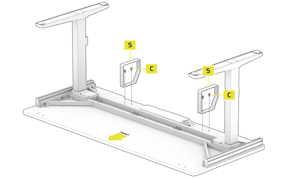
- Place the Wire Management Tray (6) over the D-Brackets (5).
- Secure the front of the Wire Management Tray (6) with two Wing Nut Screws (F).

- Secure the rear of the Wire Management Tray (6) with two M6 10mm Bolts (B).

3:安裝控制器和電源供應器
為完成此步驟,將使用下列硬體和工具:

M4 15mm 螺栓 (2x)

M6 15mm 螺栓 (2x)

控制器 (1x)

電源供應器 (1x)

電源線 (1x)
棘輪扳手和 5mm 六角銼刀 (1x)
5mm 六角工具 (1x)

六角 / 十字組合工具 (1x)

纜線夾 (6x)
(4x 配備 Platform:4)
- 如圖所示,將控制器(K) 放在桌上預先鑽好的孔上,並用兩顆 M6 15mm 螺栓(C) 固定。

- Install the Cable Clips (Z) by pushing them firmly into the holes located on the bottom side of the desk.

- Place the Power Supply (M) between the rails with the HS port facing the previously installed Controller (K) and secure it using two M4 15mm Bolts (A).

- Wire the two motors (Ω) to the M1 and M2 ports on the Power Supply (M).
- Wire the Controller (K) to the HS port on the Power Supply (M).
- Plug the Power Cable (S) to the AC port on the Power Supply (M).
- Route the cables through the Cable Clips to keep them secure.

4:安裝隔間模組和橫梁支撐桿
為完成此步驟,將使用下列硬體和工具:

橫梁支撐桿 (1x)

立方體模組 (1x)

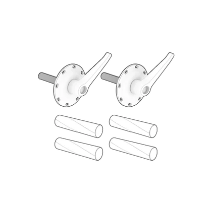
支撐桿外罩 (2x)
棘輪扳手和 5mm 六角銼刀 (1x)
5mm 六角工具 (1x)
- 將桌子翻轉到腳上。

- Slide the Cubby Module (11) assembly into the empty slot on the tabletop. The module will click once it is fully seated.

- Attach the Crossbeam Support Bar (7) by aligning its large holes over the half-threaded bolts on the rear of the legs.
- Push the Crossbeam Support Bar (7) down until it is even on both sides.
- Once secure, tighten the bolts fully.

- Carefully but firmly snap the Support Bar Covers (Q) over the ends of the Crossbeam Support Bar (7).

5:T 型通道導軌組件
為完成此步驟,將使用下列硬體和工具:

T 型通道軌道 (1x)

左右邊角支撐 (各 1x)
M6 15mm 螺栓 (2x)

棘輪螺栓 (2x)

木榫 (4x)
棘輪扳手和 5mm 六角銼刀 (1x)

3mm 六角工具 (1x)
5mm 六角工具 (1x)
- 將兩個木榫(R) 插入書桌左右兩端的對準孔中。
- 將左角支架(8) 放到木榫(R) 上。
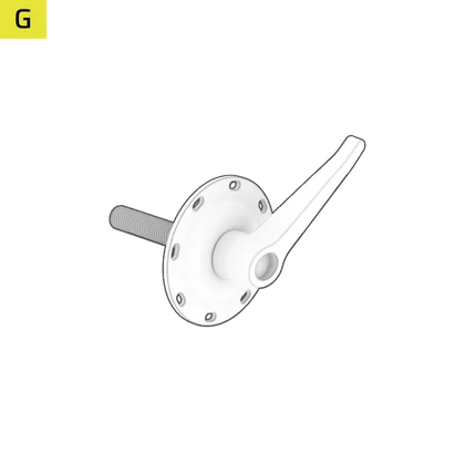
- 對準左角支撐架(8),使用棘輪螺栓(G) 將其完全固定在桌上。

- Tighten the Ratchet Bolt (G) by rotating the lever clockwise.
- Pull the Ratchet Bolt (G) lever downwards and rotate it counterclockwise.

- Repeat until secure.
- Alternatively, pull and hold the Ratchet Bolt (G) lever down and tighten it using the 5mm Hex Tool (X).

- Slide the T-Channel Rail (2) over the horizontal T-Nuts on the Left Corner Support (8) but do not tighten the set screws inside the T-Nuts yet.

- Slide the T-Channel Rail (2) over the horizontal T-Nuts on the Right Corner Support (8) but do not tighten the set screws inside the T-Nuts yet.
- Lower the Right Corner Support (8) with the attached T-Channel Rail (2) onto the Wood Dowels (R) and secure it fully to the desk using the Ratcheting Bolt (G).

- Using a 3mm Hex Tool (W), tighten the four set screws inside the T-Nuts until the T-Channel Rail (2) is rigid and sturdy.

6:T 型螺帽、電源插座和電線管理安裝 (選購)
要完成此步驟,將使用下列硬體:
**某些機型需另外購買

3 埠電源插座 (1x)

M6 10mm 螺栓 (10x)

M6 黑色 T 型螺帽 (10x)

電源線滑軌安裝 (1x)

桌上型電源插座 (1x)

直線電纜通道 (2x)

彎曲電纜通道 (2x)

小型電線管理托盤 (2x)
(1x 搭配平台:4)

搭扣粘扣帶 (10x)

黏扣帶 (10x)
3mm 六角工具 (1x)
5mm 六角工具 (1x)
六角 / 十字組合工具 (1x)
T 型螺帽安裝
T 型螺帽可讓您在平台的 T 型槽軌道系統上增加配件和延伸件。黑色 T 型螺帽為 M6 螺紋,用於組裝延伸件和配件。銀色 T 型螺帽為四分之一英吋螺紋,與 Elgato 支架產品相容。
若要在 T 型槽軌上新增並固定 T 型螺帽,請遵循下列步驟:


1.水平旋轉 T 型螺帽。
2.將 T 型螺帽側向滑入 T 型槽軌。


3.將 T 型螺帽放入插槽後,將其旋回正確方向。
4.使用 3 公釐六角工具,鎖緊 T 型螺帽內的固定螺絲,將其固定到位。
電源插座和電線管理安裝
3 埠電源插座可夾在桌上,或連接到 T 型通道導軌系統。

將 3 埠電源插座夾在桌上 (選購)
- 在桌上找一個合適的位置,順時針擰緊手把螺絲,將電源插座桌上固定座(I) 與安裝好的 3 埠電源插座(9) 固定在一起。
- 將電源線插入電源插座。

將 3 埠電源插座安裝至導軌系統 (選購)
- 使用六角 / 十字組合工具(Y),鬆開並取下電源插座桌上型固定座(I) 的十字中心螺絲,然後將 3 埠電源插座(9) 從固定板中滑出。
- 將兩個 M6 黑色 T 型螺帽(E1) 插入 T 型槽軌(2) 的背面。先不要鎖緊固定螺絲。

- Align the mounting bracket holes of the Power Strip Rail Mount (H) with the holes in the M6 Black T-Nuts (E1).
- Loosely secure the Power Strip Rail Mount (H) to the M6 Black T-Nuts (E1) by screwing in two M6 10mm Bolts (B) and slide the Power Strip Rail Mount (H) to the desired position.
- Slide the 3-Port Power Strip (9) onto the mounting bracket of the Power Strip Rail Mount (H) from the open side and secure it with the previously removed Phillips center screw.
- Tighten all the bolts.

安裝小型電線管理托盤 (選購)
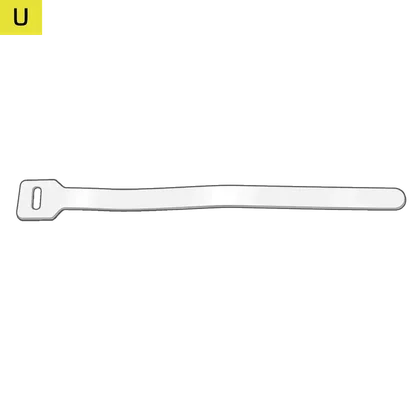
您可以使用隨附的小型電線管理托盤(N),利用隨附的黏扣帶(T和U) 將纜線綁住,以清理工作空間。
- 將兩個 M6 黑色 T 型螺帽(E1) 插入 T 型槽軌(2) 的背面。先不要鎖緊固定螺絲。
- 將小型電線管理托盤(N) 的安裝孔對準 M6 黑色 T 型螺帽(E1) 的孔。
- 擰入兩個 M6 10mm 螺栓(B),將小型電線管理托盤(N) 鬆緊固定在 M6 黑色 T 形螺帽(E1) 上。
- 將小型電線管理托盤(N) 滑動到所需位置。
- 鎖緊兩個 M6 10mm 螺栓(B),將小型電線管理托盤(N) 固定在 M6 黑色 T 型螺帽(E1) 上。
- 依照相同程序安裝第二個小型電線管理托盤(N)。

連接線槽 (選購)
您可以使用隨附的纜線通道(L1和 L2),利用隨附的黏扣帶(T和U) 將纜線綁住,清理工作空間。直線(L1) 和彎曲線纜通道(L2) 可以扣在一起,幫助您在角落支撐物下方佈線和隱藏線纜。

- 將兩個 M6 黑色 T 型螺帽(E1) 插入 T 型槽軌(2) 的背面。先不要鎖緊固定螺絲。
- 將直線電纜通道(L1) 的安裝孔對準 M6 黑色 T 型螺帽(E1) 的孔。
- 擰入兩個 M6 10mm 螺栓(B),將直線電纜通道(L1) 鬆緊固定在 M6 黑色 T 形螺帽(E1) 上。
- 將纜線通道(L1和 L2)滑動到所需位置。
- 鎖上兩個 M6 10mm 螺栓(B),將直線電纜通道(L1) 固定在 M6 黑色 T 型螺帽(E1) 上。
- 按照相同的流程安裝第二個 Cable Channel。

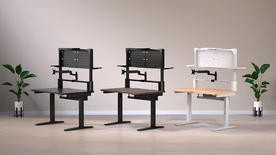
7:調整桌面高度
- 按住 Raise 按鈕(a) 升起桌面。
- 按住降低按鈕(b) 降低桌面。

- 按住 Preset 1 或 Preset 2 按鈕(e或f)五秒鐘,可將目前的高度儲存為該按鈕的預設值。

- 按下任一預設按鈕(e或f) 將桌面調整到預設高度。

預設情況下,LCD 顯示器(c) 會以公分為單位顯示桌面目前的高度。您可以執行下列動作,將控制器變更為以英吋為單位顯示高度:
- 按住 S 按鈕(d) 五秒鐘,直到 LCD 顯示幕(c) 開始閃爍 "UN"。

- 一旦 LCD 顯示幕(c) 閃爍 "UN「,按下升高或降低按鈕(a或b) 即可將單位從公分(顯示幕上顯示 」SI「)變更為英吋(顯示幕上顯示 」IN"),反之亦然。

- 按 S 按鈕(d) 鎖定所選的選項。

故障排除和錯誤代碼解釋
| E02 | 操作期間感應到震動、干擾或傾斜。 |
| 立即停止調整,讓桌子倒轉或停止移動。確認沒有障礙物後再繼續。如果錯誤訊息無法自行消失,請按住下部按鈕(b) 三至五秒鐘以重新設定。 |
| 熱門 | 觸發過熱保護。 |
| 立即停止調整。等待 18 分鐘,錯誤訊息應該會消失。如果錯誤訊息沒有自行消失,請按住下部按鈕(b) 三至五秒鐘進行重設。 |
| E20 | 觸發桌面過載保護。 |
| 繼續操作前,請先移除桌面上的重量或重物。如果在降低桌面時出現此錯誤且無法自行消失,請按住降低按鈕(b) 三至五秒鐘以重新設定。 |
| E10 | 馬達故障保護。 |
| 中斷電源。確保馬達與控制器的連接安全。重新連接電源。如果錯誤訊息無法自行消失,請按住下部按鈕(b) 三至五秒鐘以進行重設。 |
| E60 | 不同步保護。 |
| 切斷電源以重新設定。確保兩台馬達與電源供應器之間的連接,以及電源供應器與控制器之間的連接穩固。重新連接電源。如果錯誤訊息無法自行消失,請按住下部按鈕(b) 三至五秒鐘以進行重設。 |
| RES | 偵測到突然斷電。 |
| 按住下部按鈕(b) 三至五秒鐘以進行重設。 |
監視臂 - 零配件清單
* 不適用於 Platform:4
M4 25mm 螺栓 (8x)
(4x with Platform:4)

氣壓彈簧臂 (2x)
(1x 配備平台:4)

延伸臂 (2x)
(1x 與平台:4)

連接器 (1x)

安裝托架 (1x)

斜蓋 (2x)
(1x 與平台:4)

平蓋 (2x)

帶蓋 (4x)
(2x 與平台:4)

VESA 安裝 (2x)
(1x 搭配 Platform:4)

塑膠墊片 (8x)
(4x with Platform:4)

拉鍊帶 (10x)

3mm 六角工具 (1x)

4mm 六角工具 (1x)

5mm 六角工具 (1x)

6mm 六角工具 (1x)
監視器臂 - 組裝
1:安裝安裝支架和連接器
為完成此步驟,將使用下列硬體和工具:

連接器 (1x)
(僅限 Platform:6)

安裝托架 (1x)

4mm 六角工具 (1x)

6mm 六角工具 (1x)
- 鬆開手鈕螺絲,將安裝支架(E) 底部旋轉 180° 打開。
- 將安裝托架(E) 置於 T 型槽軌(2) 上,支柱在後方,然後將組件滑動到所需位置。
- 將安裝支架(E) 底部旋回關閉位置,並鎖緊手鈕螺絲和鎖緊螺絲。

- Loosen the Mounting Bracket (E) locking ring by holding its top part with one hand and unscrewing the bottom notched part with the other hand. Remove the ring by sliding it off the post.
- Using a 6mm Hex Tool (O), loosen the collar bolt of the Connector (D), allowing it to open a bit.

- Slide the Connector (D) over the post of the Mounting Bracket (E), adjust it to the desired height and retighten the collar bolt.
- Slide the Mounting Bracket (E) locking ring over the Connector (D) and secure it.

2:組裝和連接支臂
為完成此步驟,將使用下列硬體和工具:

氣壓彈簧臂 (2x)
(1x 配備平台:4)

延伸臂 (2x)
(1x 與平台:4)

斜蓋 (2x)
(1x 與平台:4)

平蓋 (2x)
(僅限 Platform:6)

5mm 六角工具 (1x)
- 使用 5 毫米六角工具(N),卸下斜面蓋(F) 的螺栓和墊圈。小心不要弄丟墊圈。
- 如圖所示,將氣壓彈簧臂(B) 放在延伸臂(C) 的插口上。
- 使用先前取下的螺栓和墊圈固定組件,並鎖緊。
- 按照相同的步驟,組裝第二個臂 (僅限平台:6)。

如果您要組裝雙螢幕臂 ...
- Using a 5mm Hex Tool (N), remove the bolt and washers of the Flat Cover (G). Be careful not to lose the washers.
- Slide the assembled arm over the post of the Connector (D).
- Insert the Flat Cover (G) and secure it with the previously removed bolt and washers. Make sure the Flat Cover (G) sits flush in the opening.
- Tighten the Flat Cover (G) bolt.
- Following the same procedure, attach the second arm.

如果您要組裝單一顯示器臂 ...
- Loosen the Mounting Bracket (E) locking ring and adjust it to the desired height position.
- Tighten the Mounting Bracket (E) locking ring to secure it.
- Slide the assembled arm over the post of the Mounting Bracket (E).

3:安裝顯示器
要完成此步驟,將使用下列硬體:

M4 25mm 螺栓 (8x)
(4x with Platform:4)

VESA 支架 (2x)
(1x 配備平台:4)

塑膠墊片 (8x)
(4x with Platform:4)
- 從您的 VESA 相容螢幕上取下螢幕底座。
- 將 VESA 固定座(I) 鎖在顯示器背面,確保固定板較平整的一面朝向顯示器頂部。

- Slide the monitor into the opening on the head of the Gas Spring Arm (B) while pulling the pin to fully secure and lock the monitor into place.

4: 彈簧張力調整和電纜管理
要完成此步驟,將使用下列硬體和工具:

帶蓋 (4x)
(2x 與平台:4)
4mm 六角工具 (1x)
- 若要調整氣壓彈簧臂(B) 的張力,請將彈簧臂向下傾斜,露出調整螺栓。
- 逆時針轉動螺絲增加彈簧張力。順時針轉動螺絲,減小彈簧張力。

- Tuck away the cable from your monitor into the rubber push-fit channel on the Extension Arm (C).
- On the Gas Spring Arm (B), hide the monitor cable into the metal channel and cover it by snapping in a Strip Cover (H).

附加功能
Platform 系列辦公桌包括兩種選購配件所提供的實用附加功能。若要瀏覽相容產品 (需另行選購),請造訪www.elgato.com。
要安裝 Elgato 配件,請使用下列硬體:

1/4" 20 銀色 T 型螺帽 (6x)

Elgato 軟臂轉接器 (1x)
Elgato 多重安裝轉接器 (2x)
elgato 彈臂轉接器
- 使用銀色 1/4" 20 銀色 T 型螺帽(E2),將 Elgato 柔性支撐臂轉接器(O) 安裝到 T 型槽軌(2) 上,安裝到角支撐(8) 頂部的預螺紋孔上,或安裝到監視器支撐臂安裝托架(E) 頂部的預螺紋孔上

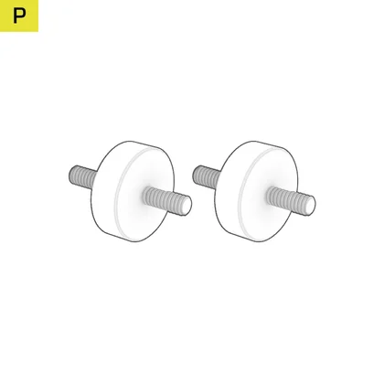
elgato 多安裝轉接頭
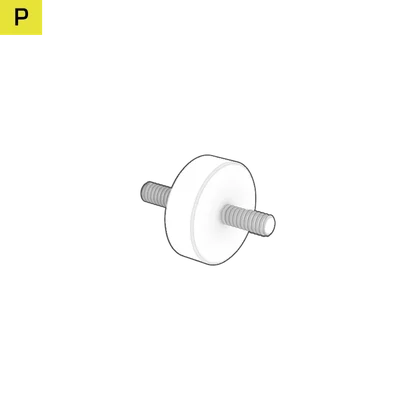
- 首先卸下 Elgato Multi Mount 產品底部的三顆螺絲。
- 使用銀色 1/4" 20 銀色 T 型螺帽(E2) 將 Elgato 多重安裝轉接器(P) 安裝到 T 型槽軌(2) 上,或安裝到角落支撐架(8) 頂端的預螺紋孔上。

辦公桌延伸和側掛板套件 - 零配件清單
若要增加 Platform 書桌的面積,您可以在一邊或兩邊增加延伸板或掛板 (需另行選購)。

大型清單

辦公桌延伸 (2x)

T 型支架 (2x)

側掛板 (2x)
小物品清單
M6 10mm 螺栓 (12x)

釘板按鈕安裝 (3x)
M6 黑色 T 型螺帽 (12 個)

短掛板鉤 (3x)

長掛板鉤 (3x)

L 形掛板鉤 (4x)

闊掛板鉤 (2x)

掛板多用鉤 (1x)
直線通道 (1x)
弧形纜線通道 (1x)
釦式黏扣帶 (5x)

拉鍊帶 (10x)
3mm 六角工具 (1x)
5mm 六角工具 (1x)
組裝擴充套件和掛板套件
1: 安裝桌用加長桿
要完成此步驟,將使用下列硬體和工具:

辦公桌延伸 (2x)

M6 10mm 螺栓 (6x)

M6 黑色 T 型螺帽 (6x)
5mm 六角工具 (1x)
- 將三個 M6 黑色 T 型螺帽(E1) 插入桌子下方的側軌,標示在較粗的垂直線所指示的位置,如下圖所示。
- 僅將兩個 M6 10mm 螺栓(B) 插入頂部的兩個黑色 M6 T 型螺帽(E1),並將其擰入約一半。

- Place the Desk Extension (12) over the half-screwed M6 10mm Bolts (B).
- Push the Desk Extension (12) so that the M6 10mm Bolts (B) wedge into the narrower grooves of the mounting holes.

- Insert an M6 10mm Bolt (B) into the bottom mounting hole of the Desk Extension (12).
- Secure the Desk Extension (12) by tightening all three M6 10mm Bolts (B).

- Repeat the process if you wish to mount an additional Desk Extension on the opposite side of the desk.
2: 安裝側掛板
要完成此步驟,將使用下列硬體和工具:

T 型支撐架 (2x)

側掛板 (2x)

M6 10mm 螺栓 (12x)
M6 黑色 T 型螺帽 (6x)

短掛板鉤 (3x)

長掛板鉤 (3x)

L 形掛板鉤 (4x)
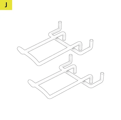
闊掛板鉤 (2x)

掛板多用鉤 (1x)
3mm 六角工具 (1x)
- 將三個 M6 黑色 T 型螺帽(E1) 插入桌子下方的側軌,標示在較粗的垂直線所指示的位置,如下圖所示。

- Secure the T-Support (13) to the M6 Black T-Nuts (E1) using three M6 10mm Bolts (B).
- Align the Pegboard (14) to the T-Support and secure it using three M6 10mm Bolts (B), as shown on the image below.

- Repeat the process if you wish to mount an additional Side Pegboard (14) on the opposite side of the desk.
- Mount the hooks onto the Side Pegboard (14) by inserting them through the holes. You can use any position on the Pegboard.
額定功率
輸入電壓:AC100-240V
頻率:50-60Hz/4A (最大值)
保固

平台系列辦公桌有 5 年保固。
法律
©2023-2025 CORSAIR MEMORY, Inc.商標屬於其各自所有者。保留所有權利。
相關內容