-
CASE SPECIFICATIONS
-
ACCESSORY KIT CONTENTS
-
CASE EXPANDED VIEW
-
PANEL INSTALLATION / REMOVAL
-
MOTHERBOARD INSTALLATION
-
MAGNETIC STRIP INSTALLATION
-
TOP-MOUNTED FRONT I/O CABLES INSTALLATION
-
FAN INSTALLATION
-
RADIATOR INSTALLATION
-
INSTALLATION OF STORAGE DEVICES AND CONTROLLERS
-
POWER SUPPLY INSTALLATION
-
GRAPHICS CARD INSTALLATION
-
CONNECTING YOUR FANS
-
MAINTENANCE
-
FREQUENTLY ASKED QUESTIONS
-
SPARE PARTS LISTING
-
WARRANTY
-
LEGAL
- RELATED CONTENT
MANUAL | QUICK START GUIDE
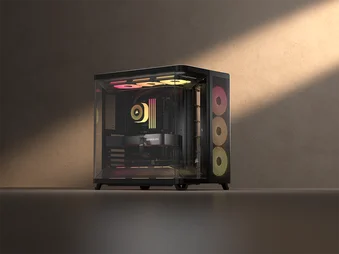
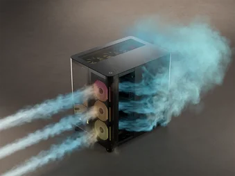
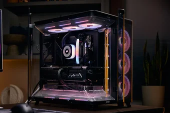
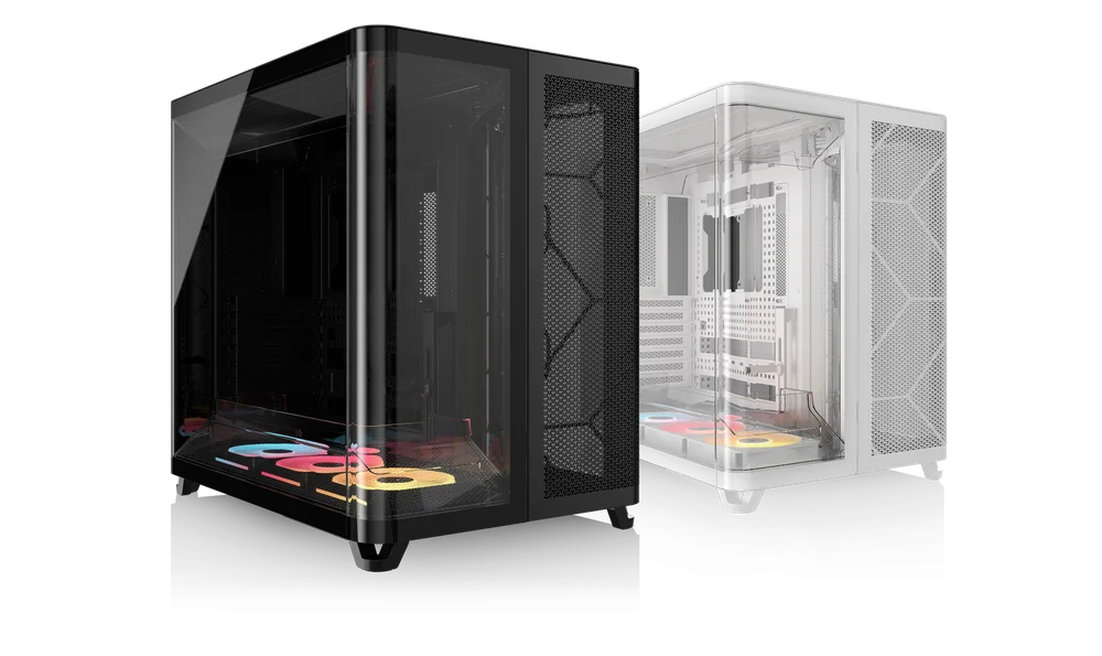
CORSAIR AIR 5400 SERIES
TRIPLE CHAMBER MID-TOWER CASE
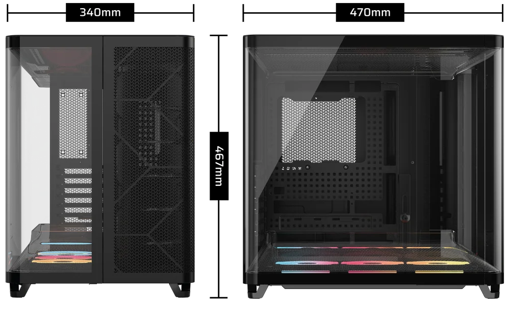
CASE SPECIFICATIONS
|
Height |
467mm |
|
Width |
340mm |
|
Length |
470mm |
|
Maximum GPU Length |
360mm |
|
Maximum CPU Cooler Height |
180mm |
|
Maximum PSU length |
200mm |
|
PCI Slot Configuration |
7x Horizontal |
|
Motherboard Compatibility |
- Mini-ITX - Micro-ATX - ATX - E-ATX (305mm x 277mm) - ASUS BTF - MSI PROJECT ZERO - GIGABYTE PROJECT STEALTH |
|
Hard Disk Drives |
1x |
|
2.5" Solid State Drives |
2x |
|
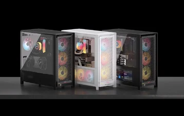
Colors Available |
- White - Black |
|
Front and Left Side Panel Material |
Tempered Glass with Shatter Safety Film |
|
Rear Cable Space |
134mm |
|
Dust Filters |
- Bottom (Pre-installed) - Front (Included in the Accessory Kit) |
|
Top-mounted Front I/O |
- 2x USB 3.2 Gen 1 Type-C - 1x USB 3.2 Gen 2x2 Type-C - 1x Power Button - 1x Combo Mic / Headphone |
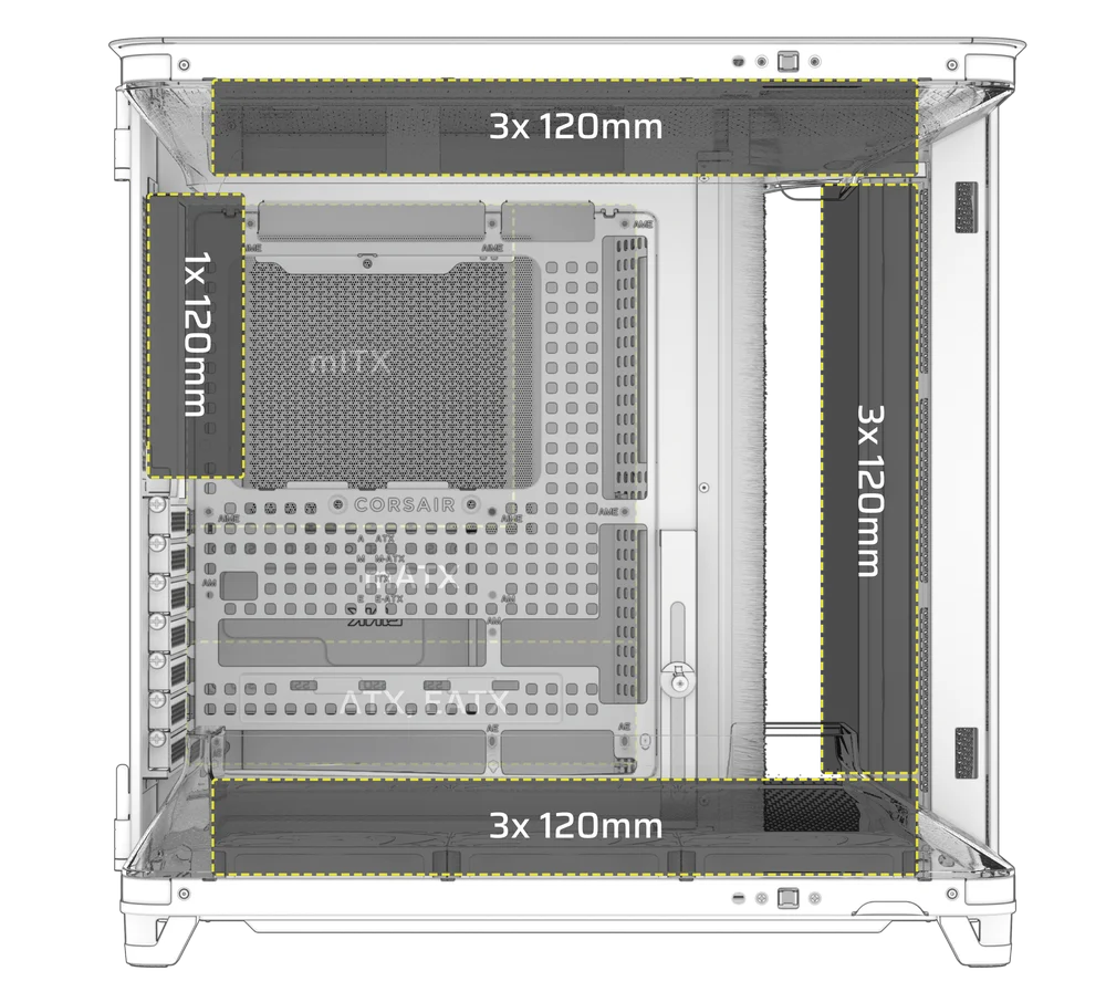
1. FAN LOCATIONS
|
Front |
Top |
Rear |
Side |
Bottom |
|
|
3x 120mm |
3x 120mm |
1x 120mm |
None |
3x 120mm |
|
2. INCLUDED FANS AND CONTROLLERS
|
|
AIR 5400 RS-R ARGB |
AIR 5400 LX-R RGB iCUE LINK |
|
Included Fans |
3x RS120-R (Pre-installed) |
3x LX120-R RGB fans (Pre-installed) |
|
Included Fan Controllers |
None | iCUE LINK System Hub (Pre-installed) |
3. RADIATOR COMPATIBILITY
|
Front |
Top |
Rear |
Side |
Bottom |
|
240mm 360mm |
240mm 360mm |
120mm
|
None |
240mm 360mm |
ACCESSORY KIT CONTENTS
* The Reusable Screw Toolkit (4) contains items labeled 5 through 11.
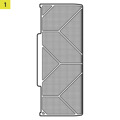
1x Front Radiator Chamber Filter
1x Reverse Connector Magnetic Strip
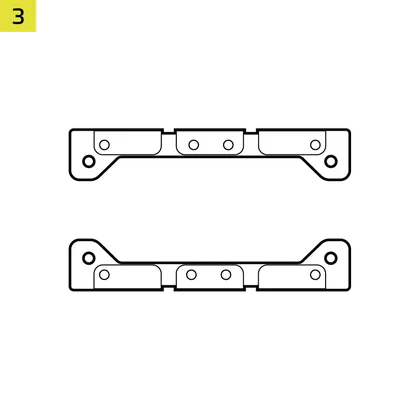
1x Rear Fan VRM Cooling Brackets
1x Reusable Screw Toolkit
(AIR 5400 LX-R RGB iCUE LINK only)
22x Motherboard / HDD Screws
(6-32 UNC; 6mm)

8x SSD Screws
(M3 x 0.5; 5mm)
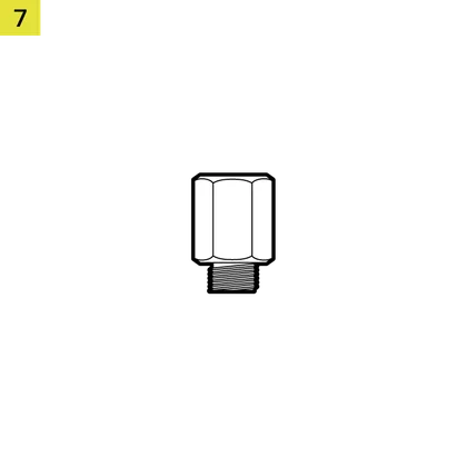
1x Spare Motherboard Standoff
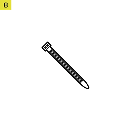
12x Zip Ties
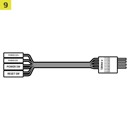
1x Top-mounted Front I/O Adapter Cable
1x Anti-sag Stabilization Arm Rubber Spacer
12x QuikTurn® Fan Screws
(AIR 5400 LX-R RGB iCUE LINK only)
3x RS120-R Fans
(Pre-installed on AIR 5400 RS-R ARGB)
3x LX120-R Fans
(Pre-installed on AIR 5400 LX-R RGB iCUE LINK)
1x iCUE LINK System Hub
(Pre-installed on AIR 5400 LX-R RGB iCUE LINK)
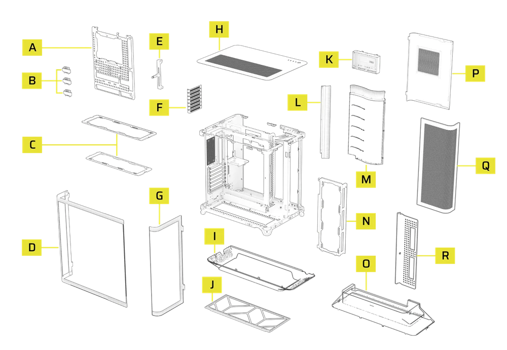
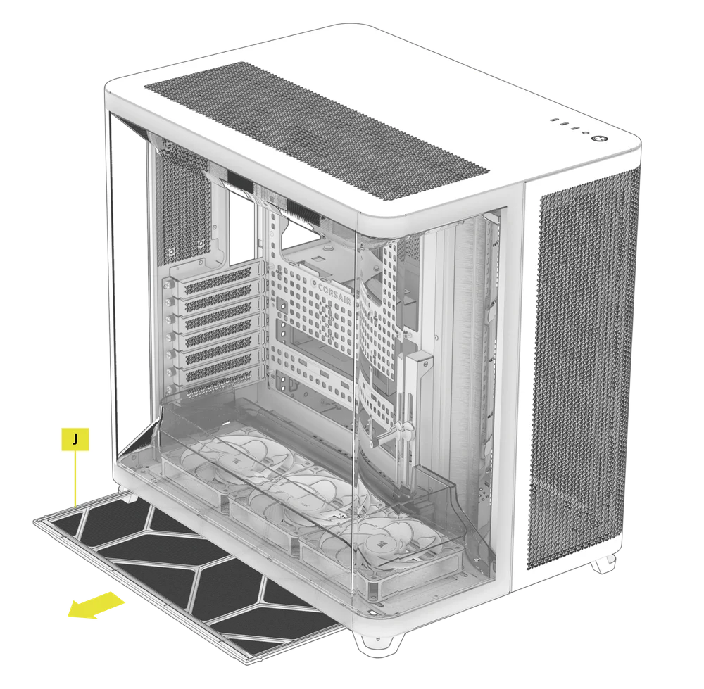
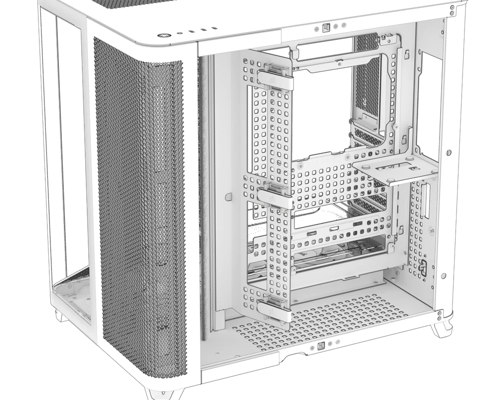
CASE EXPANDED VIEW
|
A. RapidRoute 2.0 Motherboard Tray
|
J. Bottom Filter |
| B. RapidRoute 2.0 Ratcheting Cable Organizers | K. Combination Drive Plate |
| C. Top and Bottom Fan Trays | L. Cable Management Brush |
| D. Side Tempered Glass Panel | M. Radiator Chamber Diverter Duct with Brush |
| E. GPU Anti-sag Stabilization Arm | N. Front Radiator Mount |
| F. Rear PCIe Covers | O. GPU Airflow Duct |
| G. Front Tempered Glass Panel | P. Side Steel Panel |
| H. Top Steel Panel | Q. Front Vented Steel Panel |
| I. Top Panel Airflow Duct | R. Cable Management Tray |
PANEL INSTALLATION / REMOVAL
1. FRONT-LEFT AND SIDE PANELS REMOVAL
The Side Tempered Glass Panel (D), the Front Tempered Glass Panel (G) and the Steel Side Panel (P) are mounted on hinges and open outward.
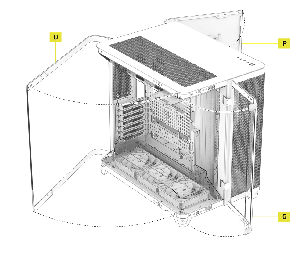
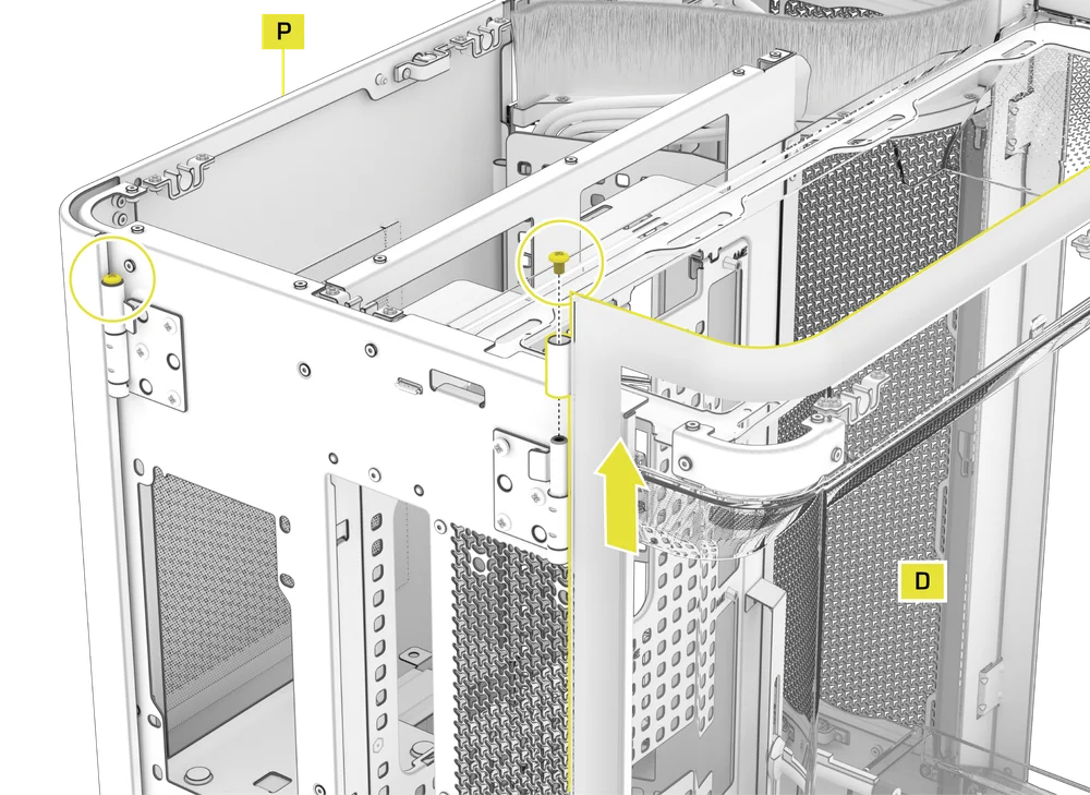
SIDE PANELS REMOVAL
The Side Tempered Glass Panel (D) and the Steel Side Panel (P) include finger recesses along the bottom edge for easy access.
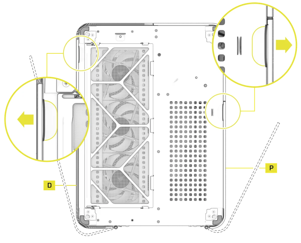
- To remove the Side Tempered Glass Panel (D) and the Steel Side Panel (P), unscrew the lock screws at the top of each hinge and lift them off.
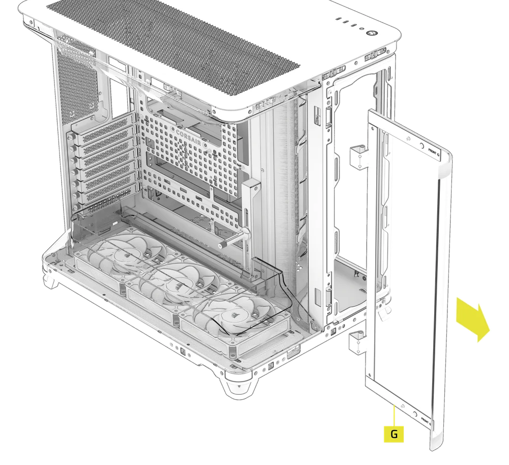
FRONT TEMPERED GLASS PANEL REMOVAL
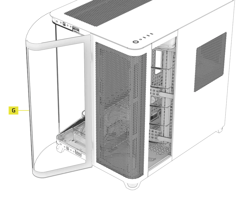
- To remove the Front Tempered Glass Panel (G) first locate the pin lock screws.
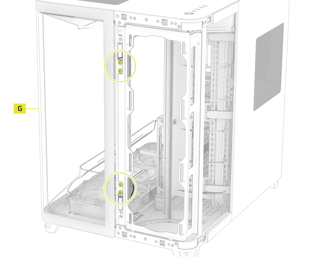
- Remove the pin lock screws and the pin lock.
- Remove the pin.
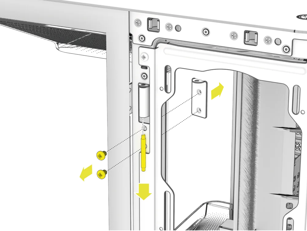
- Carefully remove the Front Tempered Glass Panel (G).
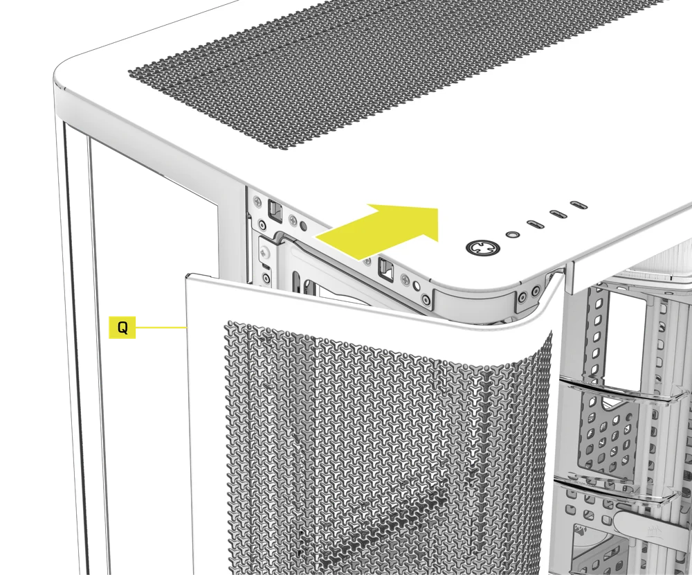
2. FRONT VENTED STEEL PANEL REMOVAL
- To remove the Front Vented Steel Panel (Q), simply pull it away from the case.
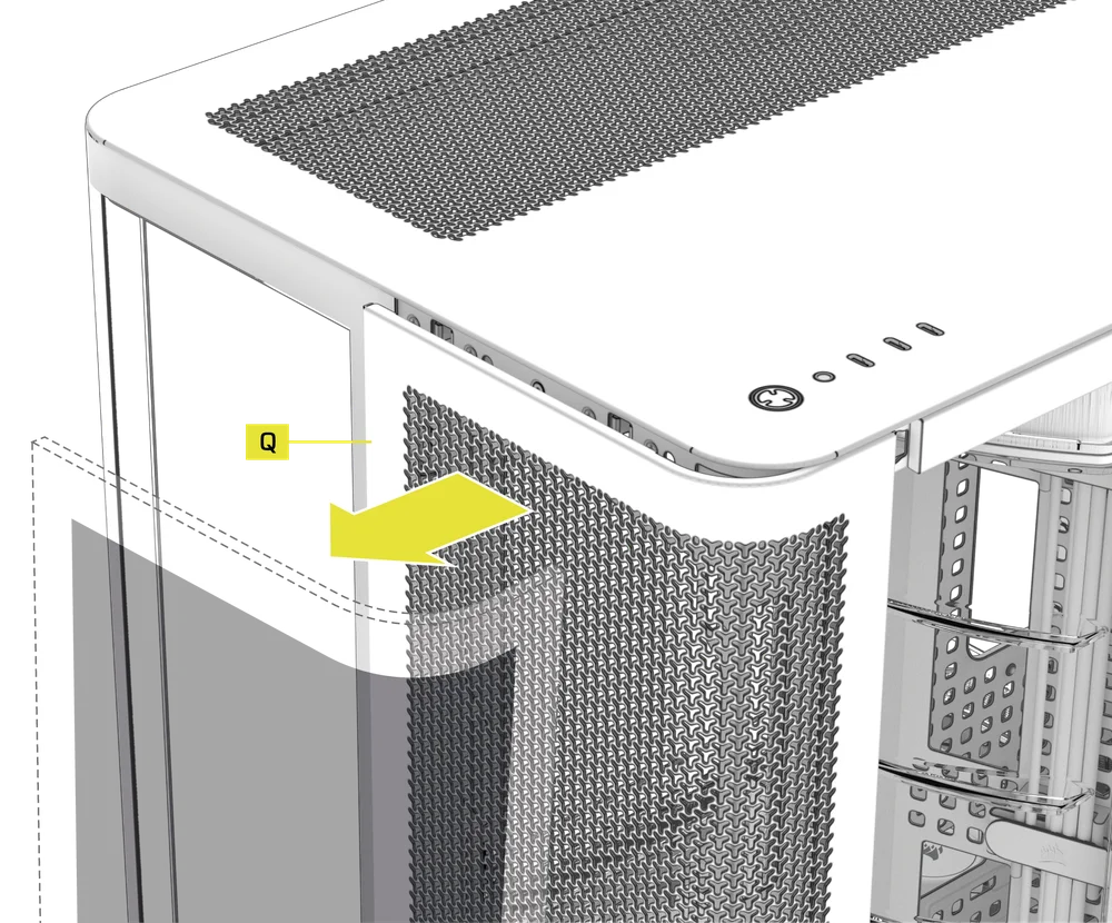
- To reinstall, hook the front panel into the right side of the case and then push the panel onto the ball-snaps.
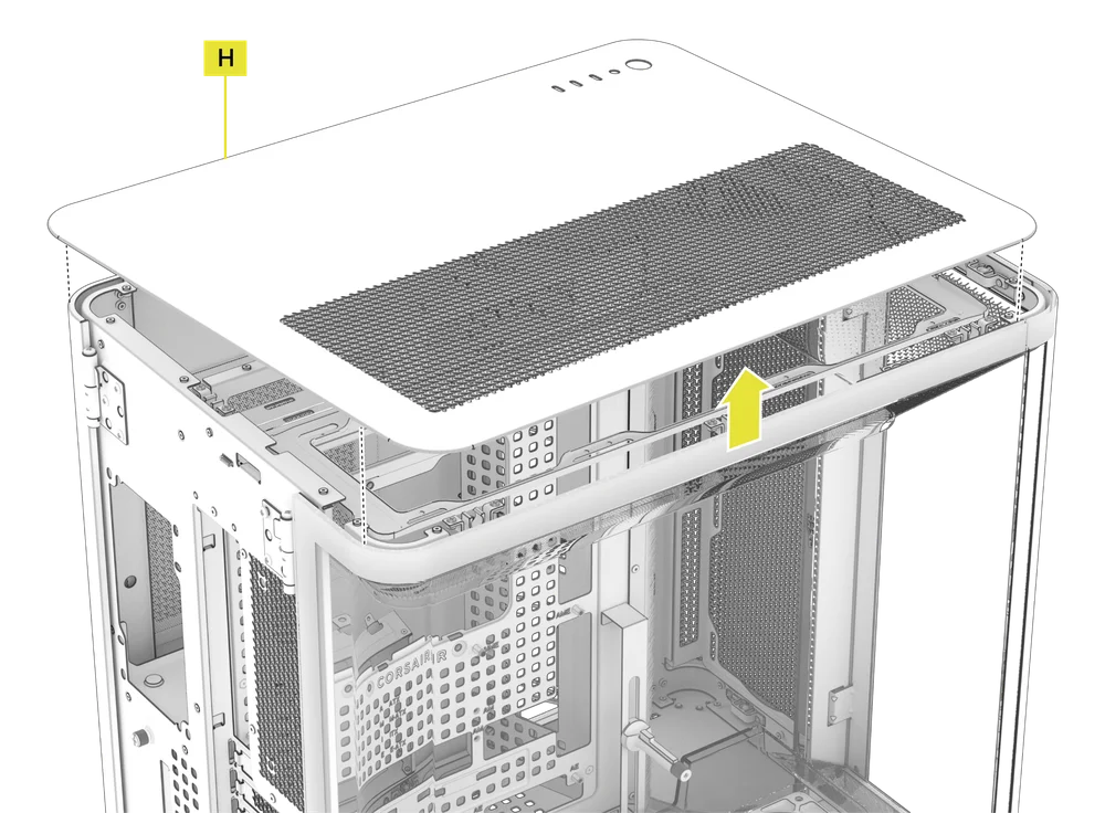
3. TOP STEEL PANEL REMOVAL
- To remove the Top Steel Panel (H), simply lift it from the rear or sides upward.
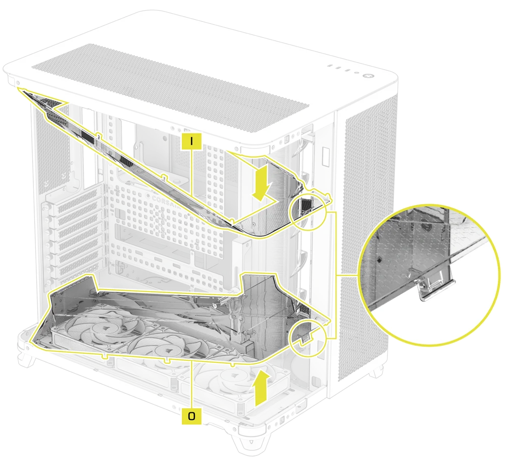
4. AIRFLOW DUCTS REMOVAL
- Both the Top Panel Airflow Duct (I) and the GPU Airflow Duct (O) can be removed by releasing the plastic clip at the front of the case and tilting the ducts inward.
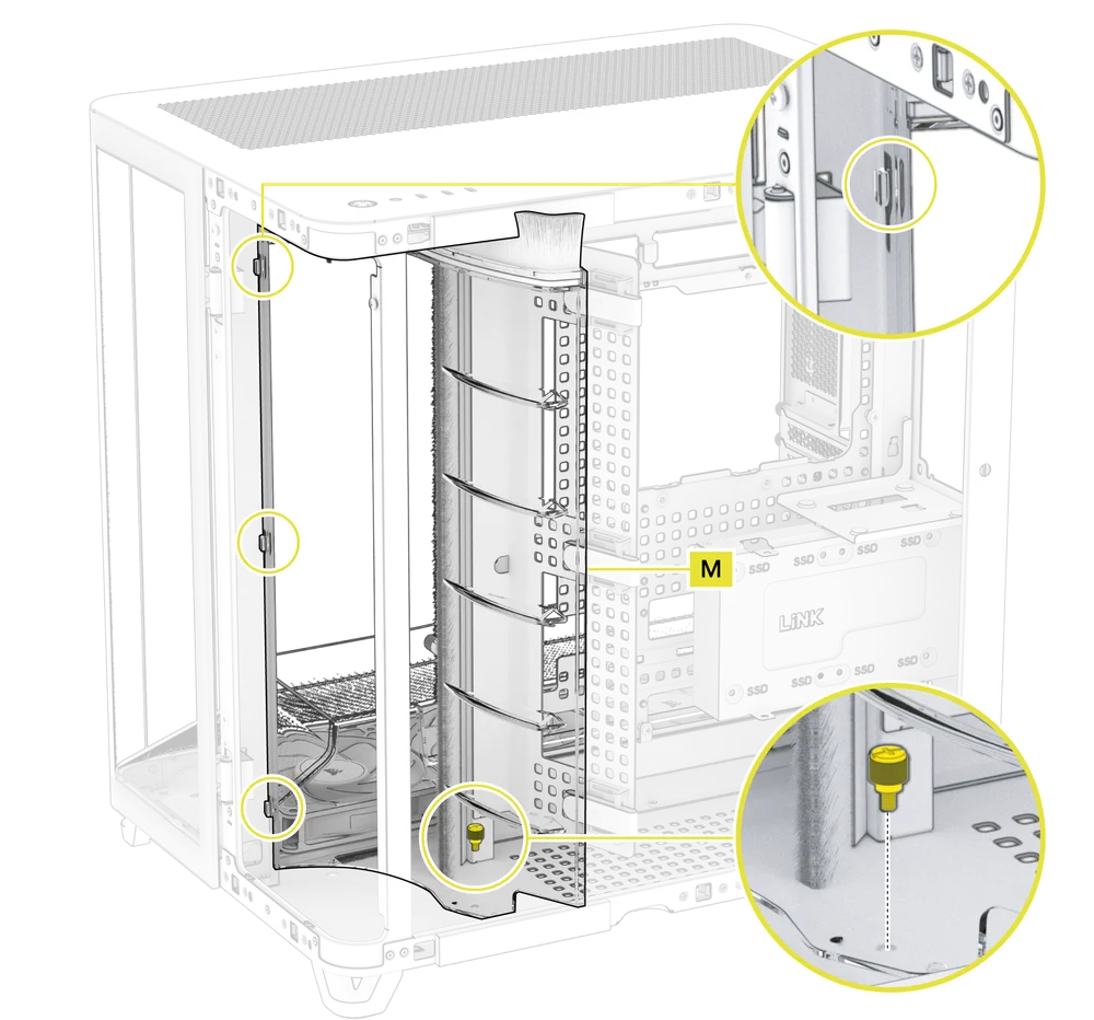
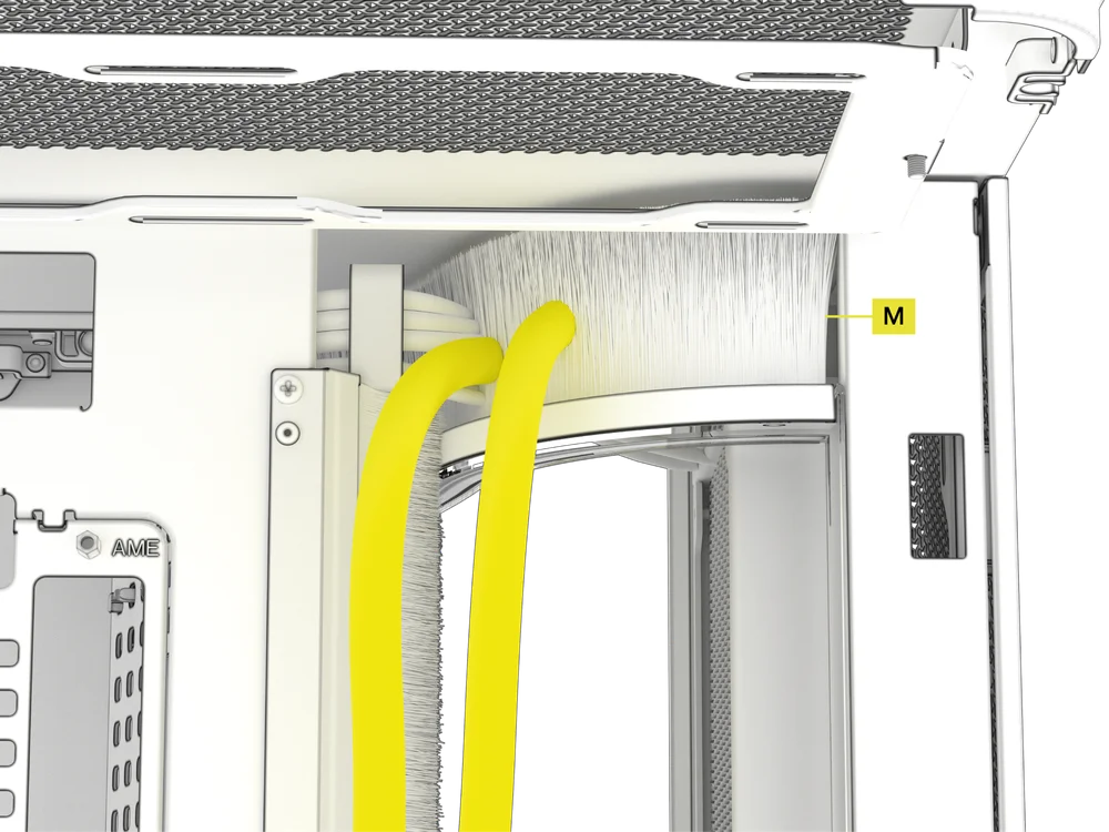
- The Radiator Chamber Diverter Duct with Brush (M) can be removed by unscrewing the captive screw at its base, then lifting it up and sliding it out of the locking pegs that secure it in the case.
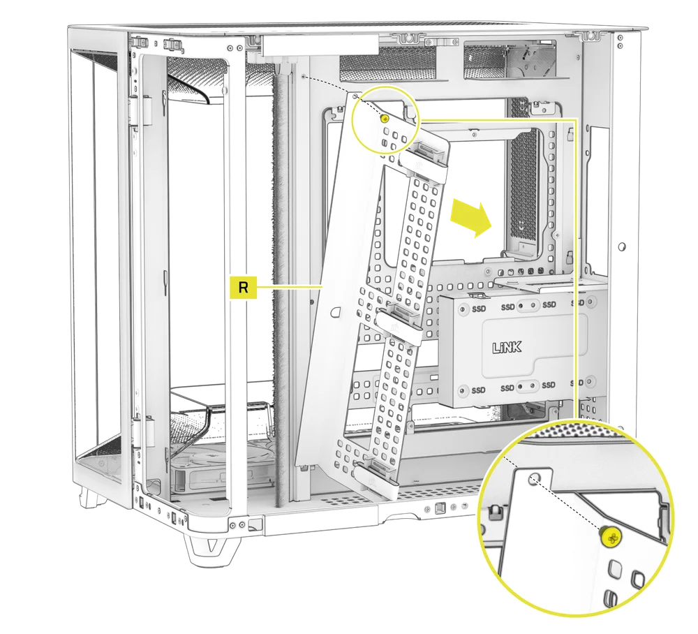
5. CABLE MANAGEMENT TRAY REMOVAL
The AIR 5400 includes a double-sided Cable Management Tray (R) sporting CORSAIR’s RapidRoute 2.0 pattern that gives you additional zip tie locations and strap mounting points.
- To uninstall the Cable Management Tray (R) for more room while building or for a different, more revealed look, unscrew the screw along the upper edge and lift the tray out.
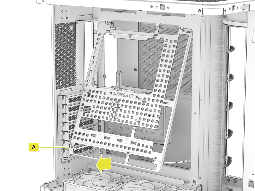
6. MOTHERBOARD TRAY REMOVAL
The RapidRoute 2.0 Motherboard Tray (A) is secured by four screws along its back.
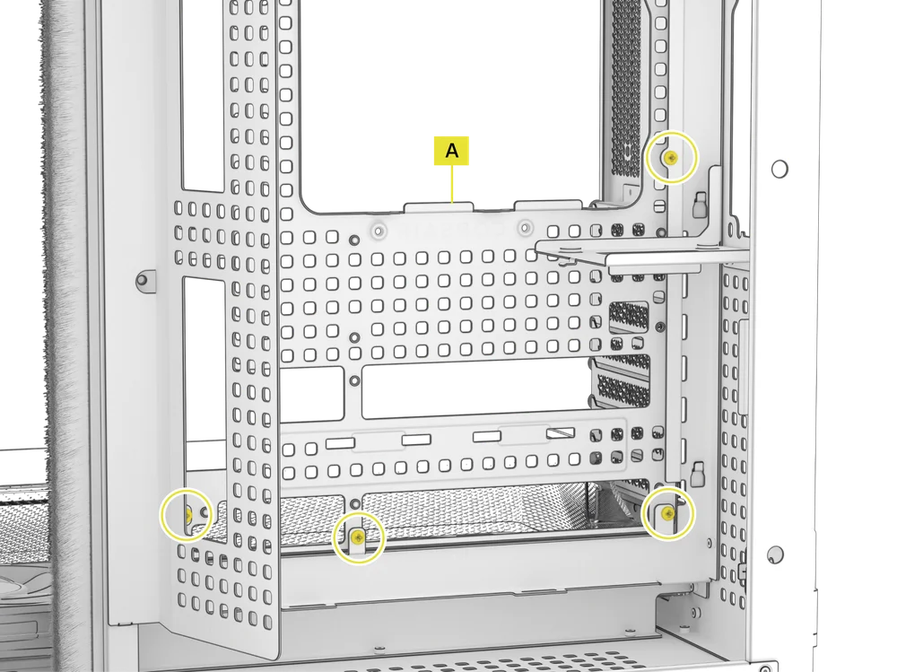
- Remove the four screws in the back and swing the RapidRoute 2.0 Motherboard Tray (A) forward to remove it from the case. Repeat these actions in reverse to re-assemble.
MOTHERBOARD INSTALLATION
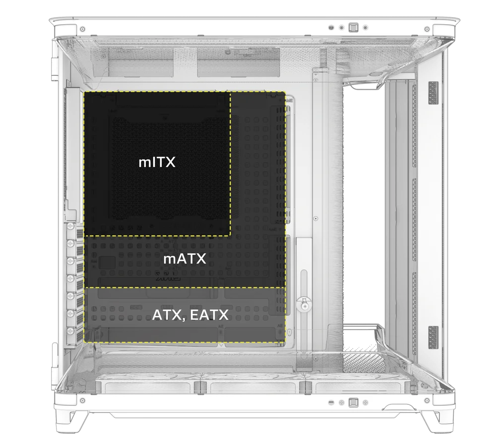
The AIR 5400 supports mITX, mATX, ATX, E-ATX motherboards, and ASUS BTF, MSI Project Zero, and GIGABYTE Project STEALTH motherboards with reverse connectors.
- Align your motherboard with the standoffs and secure it using the Motherboard Screws (8).
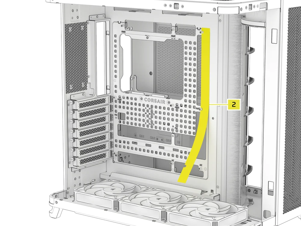
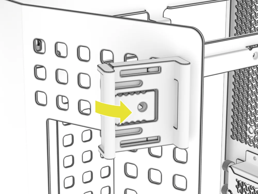
MAGNETIC STRIP INSTALLATION
The AIR 5400 includes a Reverse Connector Magnetic Strip (2), designed to cover the exposed edge of the reverse connector cutouts in the motherboard tray.
- Align the Reverse Connector Magnetic Strip (2) to your standoffs and adjust side to side to close the gap on your motherboard.
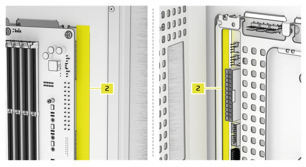
1. MOTHERBOARD WITH REVERSE CONNECTORS
If you're installing a motherboard with reverse connectors, the Reverse Connector Magnetic Strip (2) can be used to fill the gap around the 24-pin ATX port, providing a cleaner and more polished appearance.
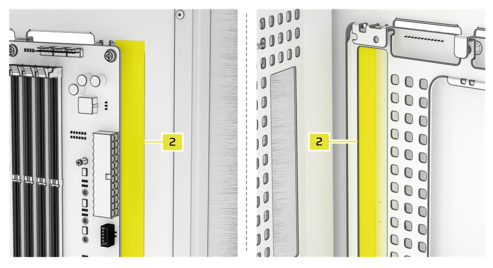
2. MOTHERBOARD WITH STANDARD CONNECTORS
When installing a standard motherboard, you can slide the Reverse Connector Magnetic Strip (2) behind the board, aligning it with the screw holes along the motherboard tray, to cover the reverse connector slot and conceal any wires running along the motherboard tray for a cleaner look.
TOP-MOUNTED FRONT I/O CABLES INSTALLATION
1. STANDARD INTEL MOTHERBOARDS
- Connect the FPANEL plug to the Top-mounted front I/O header on your motherboard, aligning it with the keyed layout. This header is often labeled JFP1 on some motherboards.
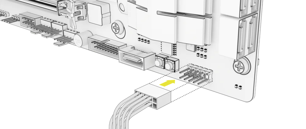
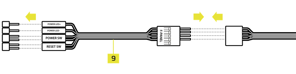
2. AMD OR NON-STANDARD INTEL MOTHERBOARDS
- Use the included Top-mounted Front I/O Adapter (9) to connect the FPANEL plug to the individual Top-mounted Front I/O header pins.
3. FRONT I/O EXPLANATION
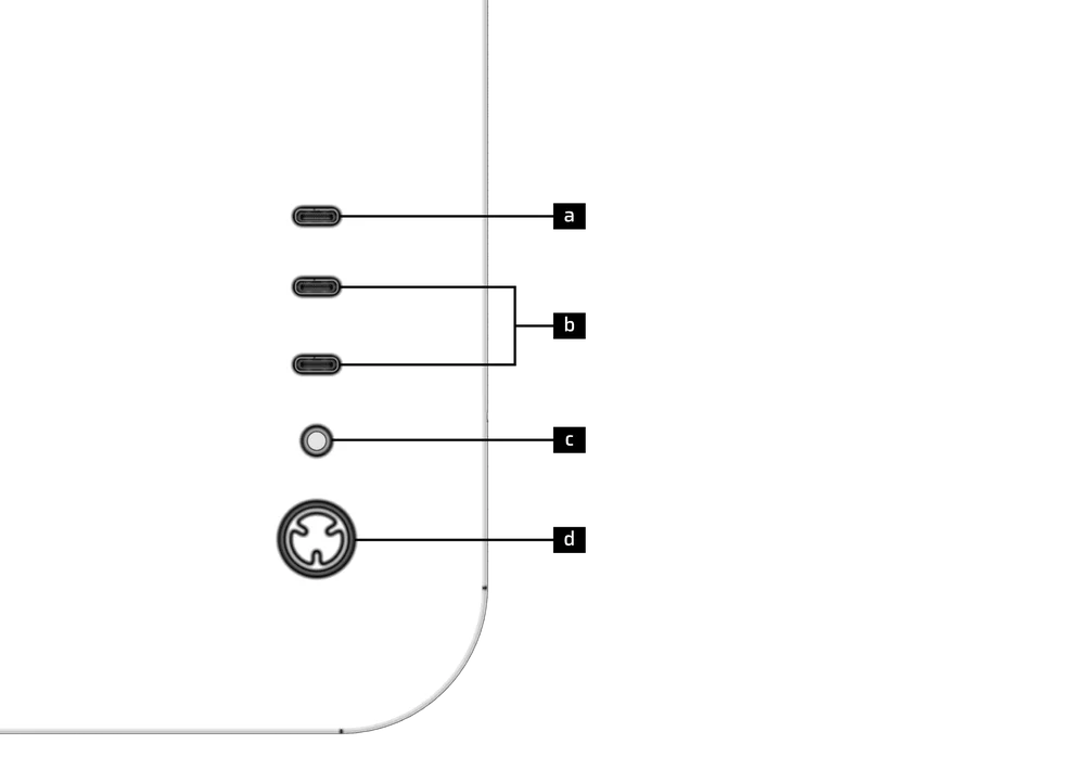
| a) 1x USB 3.2 Gen 2x2 Type-C Port (20 Gbps) | c) Headphone / Mic Combination Jack |
| b) 2x USB 3.2 Gen 1 Type-C Ports (5 Gbps) | d) Power Button + LED |
4. TOP-MOUNTED FRONT I/O CONNECTIONS
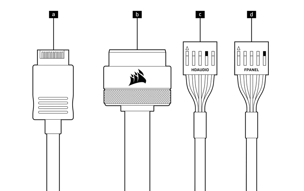
| a. USB 3.2 Type-E (20 Gbps) | c. HD Audio (Headphone, Microphone) |
| b. USB 3.0 | d. FPANEL (Power LED, Power Button) |
FAN INSTALLATION
|
Front |
Top |
Rear |
Side |
Bottom |
|
|
3x 120mm |
3x 120mm |
1x 120mm |
None |
3x 120mm |
|
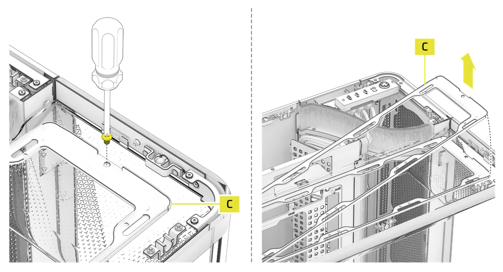
1. INSTALLING FANS ON THE TOP
- Remove the single set screw securing the Top Fan Tray (C).
- Tip and lift the Top Fan Tray (C) off the case.
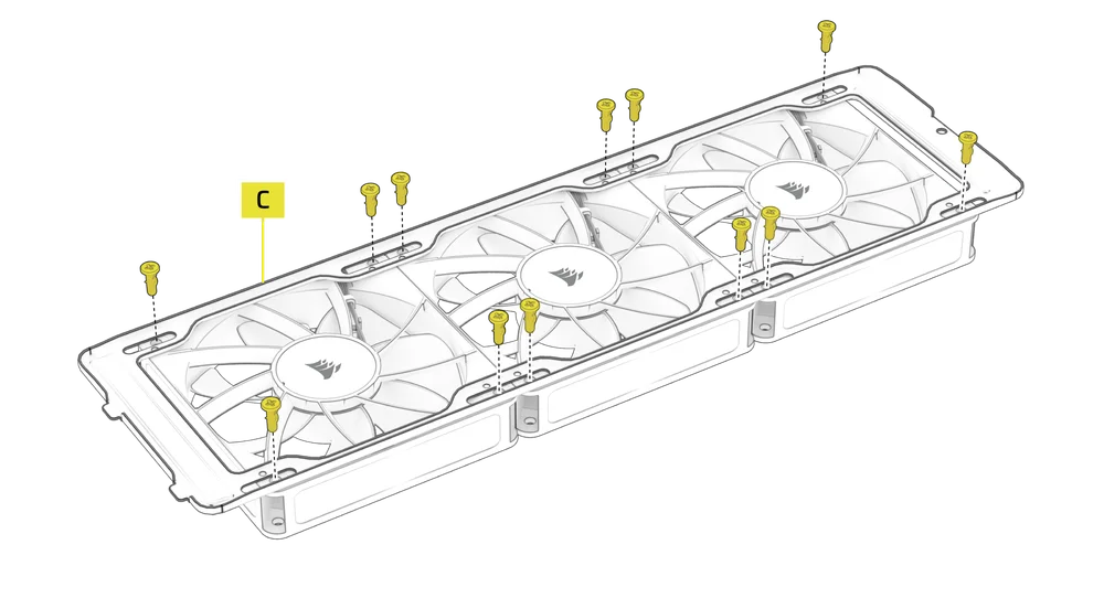
- Screw your 120mm fans into the Top Fan Tray (C) outside of the case.
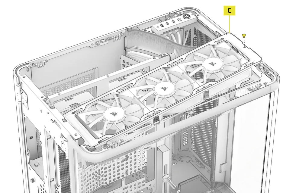
- Mount the Top Fan Tray (C) and fans back inside the case and secure it with the previously removed set screw.
TIP: Use the dots marked on the Top Fan Tray (C) to serve as centering guides.
2. INSTALLING FANS ON THE BOTTOM
The fans on the bottom are installed using the same procedure as the top fans.
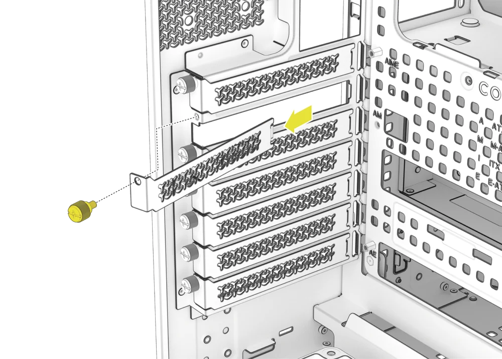
3. INSTALLING FANS IN THE REAR
The AIR 5400 supports an optional rear exhaust or intake fan by using the included brackets for a 120mm fan.
- Align the Rear Fan VRM Cooling Brackets (3), installing the bars horizontally across the fan.
- Align the fan and the brackets to the rear of the case and secure the assembly with included Motherboard / HDD Screws (5).

NOTE: The fan is obscured in the rear mount location and is only recommended for instances or builds where supplemental VRM airflow is needed, such as overclocking.
RADIATOR INSTALLATION
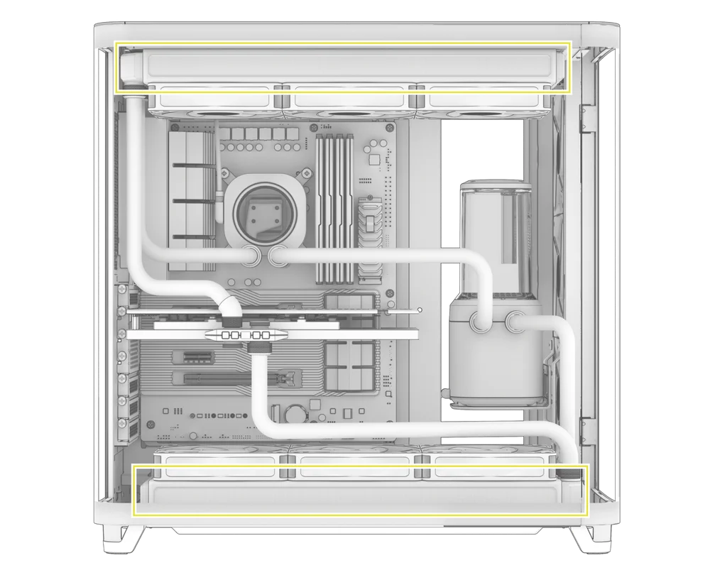
The AIR 5400 features three fully removable radiator and fan mounts in the top, bottom, and front of the case.
|
Front |
Top |
Rear |
Side |
Bottom |
|
240mm 360mm |
240mm 360mm |
120mm
|
None |
240mm 360mm |

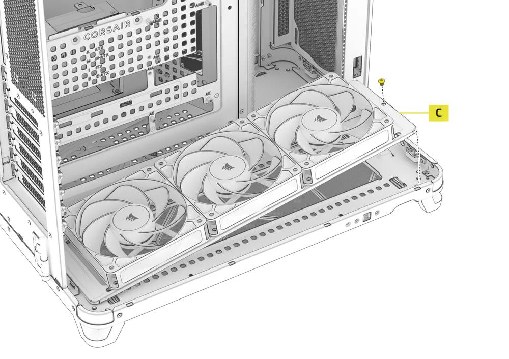
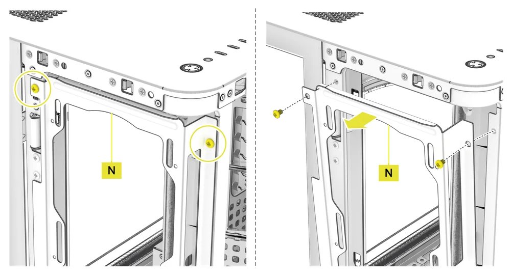
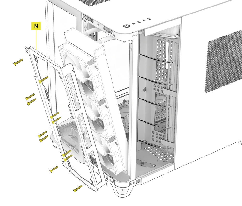
1. INSTALLING THE RADIATOR IN THE FRONT
- Remove the Front Vented Steel Panel (Q) by pulling it off the case.
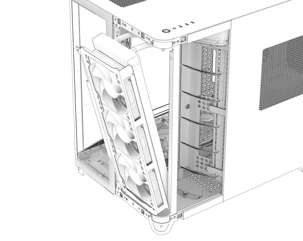
- Remove the two screws, tip the Front Radiator Mount (N) toward you, and lift it off.
- Align your radiator and fans with airflow coming from outside the case and blowing through the radiator towards the back of the case.
- Use the long fan screws in your radiator / AIO packaging to secure the radiator and fans to the Front Radiator Mount (N).
TIP: Use the dots marked on the Front Radiator Mount (N) to serve as centering guides.
TIP: Bias the radiator and the fans down to avoid any interference with the front panel I/O.
- Tip the mount including the radiator back into the chassis and secure the two set screws.
- Ensure your tubes run up and over the Radiator Chamber Diverter Duct with Brush (M).
2. INSTALLING THE RADIATOR ON THE TOP OR BOTTOM
INSTALLATION OF STORAGE DEVICES AND CONTROLLERS
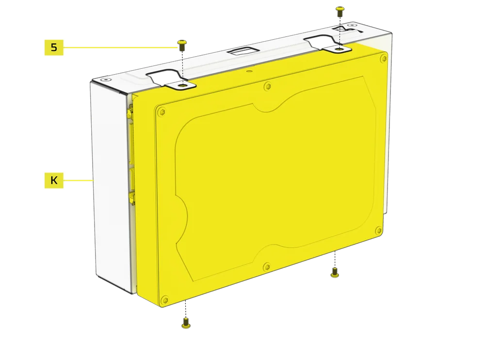
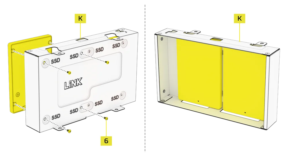
The AIR 5400 includes one Combination Drive Plate (K), that allows you to mount a single 3.5" HDD and two 2.5" SSDs simultaneously.

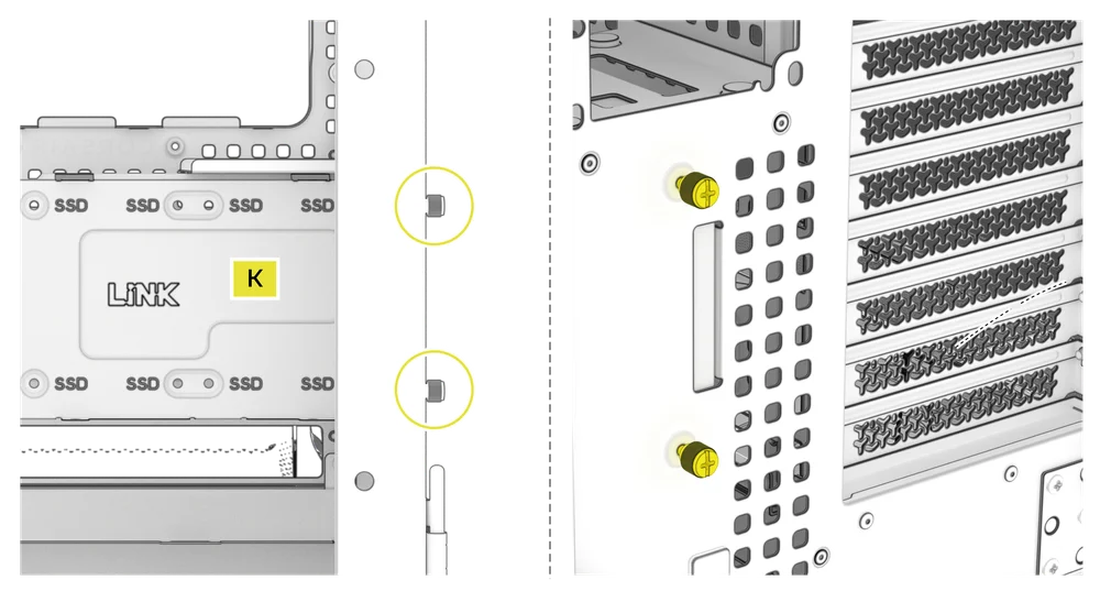
1. COMBINATION DRIVE PLATE REMOVAL
- Loosen the two captive thumbscrews located on the rear of the case to release the Combination Drive Plate (K), then remove it.
2. HDD INSTALLATION ON THE COMBINATION DRIVE PLATE
- Install the HDD on the front of the Combination Drive Plate (K) by securing it using the included HDD Screws (5) found in the accessory box.
3. SSD INSTALLATION ON THE COMBINATION DRIVE PLATE
- Install an SSD in the rear of the Combination Drive Plate (K) by securing it using the included SSD Screws (6) found in the accessory box.
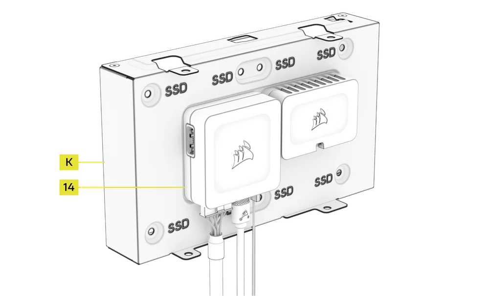
4. iCUE LINK SYSTEM HUB INSTALLATION ON THE COMBINATION DRIVE PLATE
The Combination Drive Plate (K) also serves as a mounting location for an iCUE LINK System Hub (14) or an iCUE LINK 4-Way Signal Splitter.
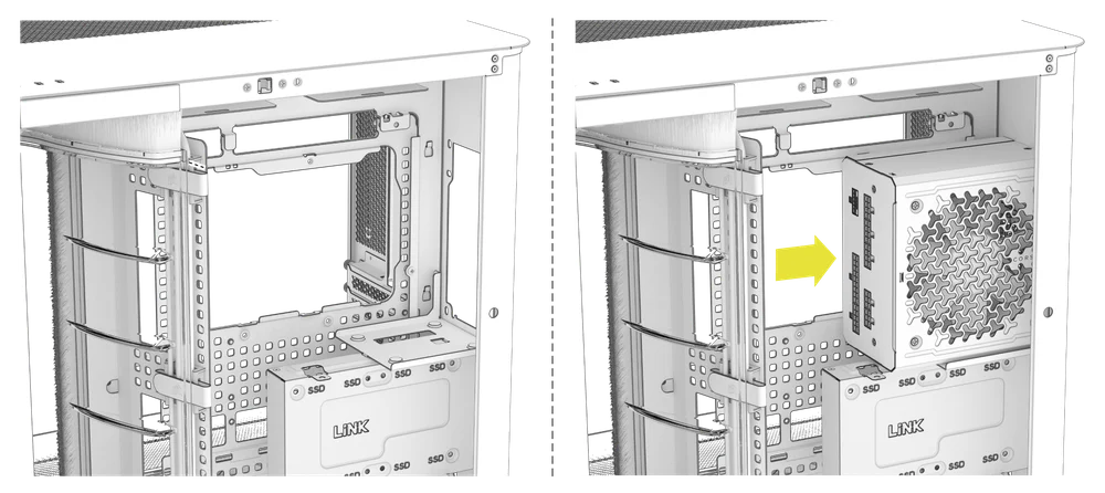
POWER SUPPLY INSTALLATION
1. STANDARD POWER SUPPLY INSTALLATION
- Install the PSU with the fan facing the side.
- Secure the power supply to the chassis with the four captive screws located on the back of the AIR 5400.
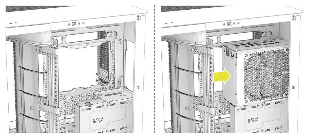
2. CORSAIR SHIFT POWER SUPPLY INSTALLATION
The AIR 5400 is fully compatible with CORSAIR SHIFT power supplies and installs identically to a standard ATX PSU.
- Install the PSU with the fan facing the side.
- Secure the power supply to the chassis with the four captive screws located on the back of the AIR 5400.
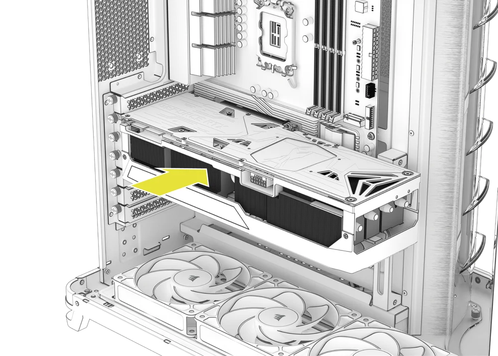
GRAPHICS CARD INSTALLATION
The AIR 5400 only supports horizontal GPU mounting configurations.
1. INSTALLING A GPU
- Remove thumbscrews and PCIe slot covers.
- Insert the card into the PCIe slot until it clicks into place with the PCIe slot's retention retention mechanism.
- Align the bracket with the PCIe slots and secure the card to the case.
2. USING THE GPU ANTI-SAG STABILIZATION ARM
- Adjust the GPU Anti-sag Stabilization Arm (E) by loosening the front-facing thumbscrew and sliding the arm up or down until it properly supports your graphics card.

If your GPU fan or other parts come into contact with the rubber arm, use the included Anti-sag Stabilization Arm Rubber Spacer (10) from the accessory box to ensure clearance from any moving parts.
- Attach the self-adhesive Anti-sag Stabilization Arm Rubber Spacer (10) to the GPU Anti-sag Stabilization Arm (E).

CONNECTING YOUR FANS
1. CONNECTING AND CONTROLLING FANS FOR AIR 5400 RS-R ARGB
Please visit the CORSAIR RS120-R ARGB Quick Start Guide for instructions on fan installation.
2. CONNECTING AND CONTROLLING FANS FOR AIR 5400 LX-R RGB iCUE LINK
Please visit the CORSAIR iCUE LINK LX-R RGB Quick Start Guide for instructions on fan installation.
MAINTENANCE
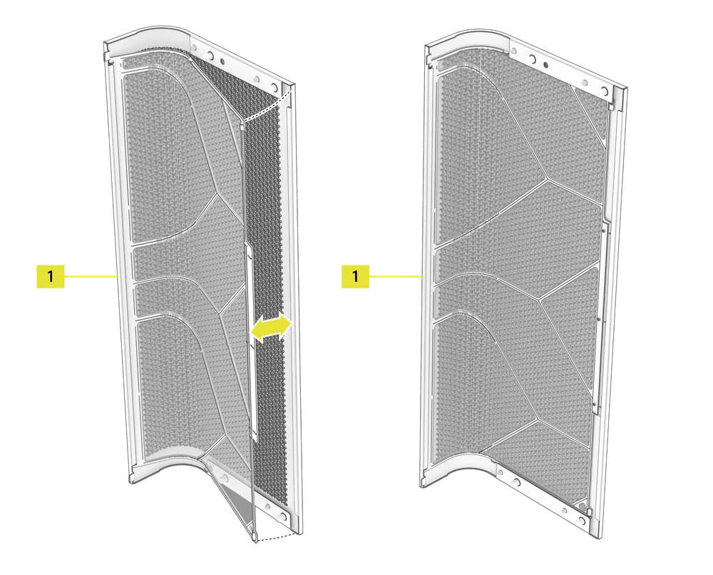
1. CLEANING YOUR CASE FILTERS
The AIR 5400 includes two removable dust filters - a Bottom Filter (J) and an optional front Fan Filter (1). Filters can be cleaned with pressurized air or water. If you rinse your filter, ensure filters are fully dry before reinstalling.
- To install or remove the Front Radiator Chamber Filter (1), slide the edge of the filter under the inner lip of the front-right panel and then tuck the filter into the opposite edge.
NOTE: The Front Radiator Chamber Filter (1) is solely for convenience and has no impact on your internal component cleanliness, other than the radiator. For maximum performance, we recommend skipping the filter and cleaning your radiator as needed. If you prefer the convenience of a filter, expect a very slight performance decrease (typically <3°C) due to increased impedance. Regardless of filter usage, the air ducts may require periodic dusting.
- To remove the Bottom Filter (J), slide the filter away from the left side of the case.
NOTE: A top filter is available, but we do not recommend its usage, as performance will suffer significantly and using exhaust fans should help mitigate even falling dust. Should you choose to add it, the spare part number can be found in the table below.
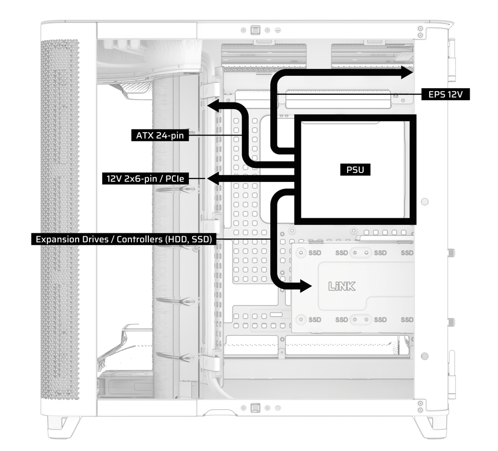
2. CABLE MANAGEMENT
RapidRoute 2.0 features CORSAIR's "squircle" mounting patter on the motherboard try and surrounding structure. Anywhere you see this patterning, you can use the holes to mount RapidRoute 2.0 accessories, similar to a pegboard.
The AIR 5400 includes several ratcheting strap mounts.
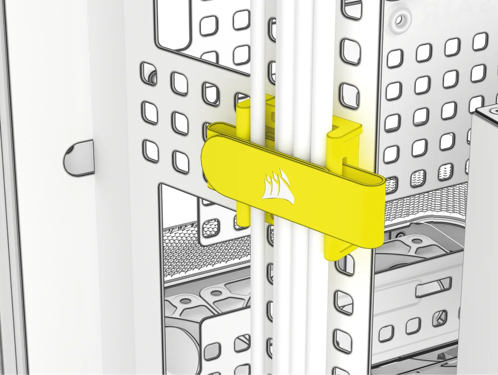
- To remove the ratcheting strap mount from the RapidRoute 2.0 pattern, remove or push the strap to the side and identify the retention plunger.
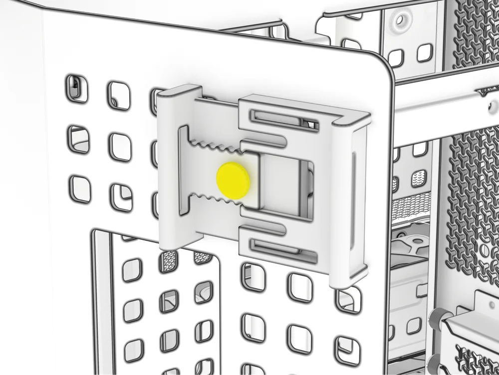
- Pull the plunger out, set it aside and do not lose it.
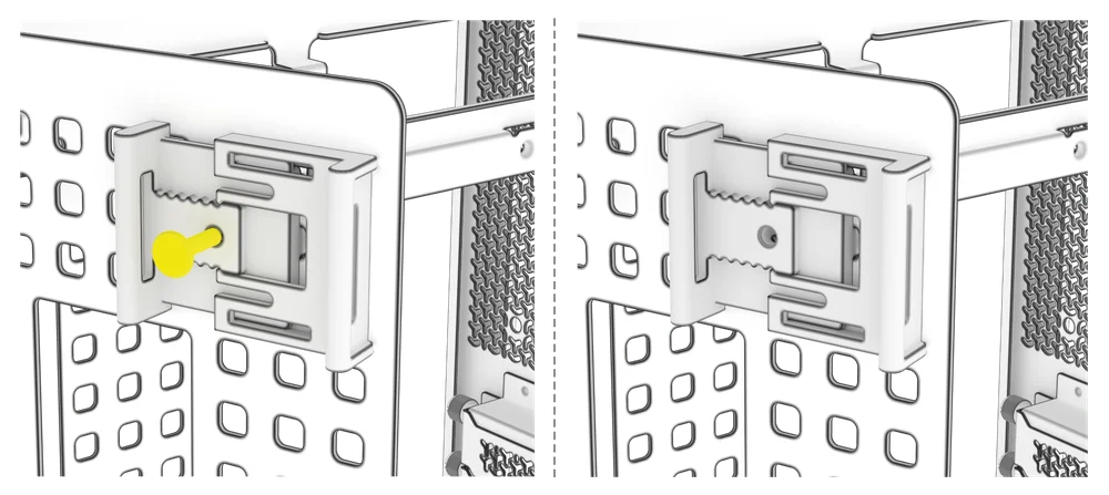
- Tilt the mount to remove and relocate it to your desired location.
3. ADDITIONAL CABLE MANAGEMENT TIPS
- Use the built-in cable management features to keep your cables tamed and out of the way of your PC’s airflow.
- Zip tie points are strategically placed for routing power cables to specific devices.
- iCUE LINK cable hooks in the top panel to securely hold iCUE LINK cables without permanent attachment.
- This case supports most reverse connector motherboards (MSI, ASUS, GIGABYTE) that feature connectors on the rear face of the board to provide you with the cleanest possible build.
- A dedicated location for your iCUE LINK System Hub keeps your controller from moving around and looks tidy.
FREQUENTLY ASKED QUESTIONS
Can I air cool in an AIR 5400?
You absolutely can, but you would not be using the case to its full abilities and would miss out on the multi-chamber benefits of piping the CPU heat outside the chassis.
What is the plastic pop-out plate that says XENEON EDGE, or LINK in older cases, used for?
This was designed for un-released external iCUE LINK device support and has been repurposed for passing the HDMI for an internally mounted XENEON EDGE LCD.
SPARE PARTS LISTING
|
CC-8901066
|
AIR 5400 Replacement Top Panel, Black
|
|
CC-8901067
|
AIR 5400 Replacement Top Panel, White
|
|
CC-8901068
|
AIR 5400 Replacement Left Side Glass Door, Black
|
|
CC-8901069
|
AIR 5400 Replacement Left Side Glass Door, White
|
|
CC-8901070
|
AIR 5400 Replacement Front Glass Door, Black
|
|
CC-8901071
|
AIR 5400 Replacement Front Glass Door, White
|
|
CC-8901072
|
AIR 5400 Replacement Top Duct, Clear
|
|
CC-8901073
|
AIR 5400 Replacement Bottom Duct, Clear
|
|
CC-8901074
|
AIR 5400 Replacement AIO Duct, Clear
|
|
CC-8901075
|
AIR 5400 Replacement HDD/SSD Mount, Black
|
|
CC-8901076
|
AIR 5400 Replacement HDD/SSD Mount, White
|
|
CC-8901077
|
AIR 5400 Replacement Right Side Deco Covers, Black
|
|
CC-8901078
|
AIR 5400 Replacement Right Side Deco Covers, White
|
|
CC-8901079
|
AIR 5400 Replacement Steel Front Panel (AIO Chamber), Black
|
|
CC-8901080
|
AIR 5400 Replacement Steel Front Panel (AIO Chamber), White
|
|
CC-8901081
|
AIR 5400 Replacement Front Dust Filter, Black
|
|
CC-8901082
|
AIR 5400 Replacement Front Dust Filter, White
|
|
CC-8901083
|
AIR 5400 Replacement Bottom Dust Filter, Black
|
|
CC-8901084
|
AIR 5400 Replacement Bottom Dust Filter, White
|
|
CC-8901085
|
AIR 5400 Top Dust Filter, Black
|
|
CC-8901086
|
AIR 5400 Top Dust Filter, White
|
|
CC-8901087
|
AIR 5400 PSU Dust Filter, Black
|
|
CC-8901088
|
AIR 5400 PSU Dust Filter, White
|
|
CC-8901089
|
AIR 5400 Replacement Ball Snaps, Black
|
|
CC-8901090
|
AIR 5400 Replacement Ball Snaps, White
|
|
CC-8901097
|
CORSAIR RS120-R ARGB, 120mm ARGB Fan, Single Pack
|
|
CC-8901098
|
CORSAIR RS120-R ARGB White, 120mm ARGB Fan, Single Pack
|
|
CO-9051053-WW
|
iCUE LINK LX120-R RGB 120mm PWM Reverse Fan Expansion - White
|
|
CO-9051049-WW
|
iCUE LINK LX120-R RGB 120mm PWM Reverse Fan Expansion
|
|
CO-8950034
|
RS/RS ARGB PWM Extension Cable 3-pack, Black
|
|
CO-8950035
|
RS/RS ARGB PWM Extension Cable 3-pack, White
|
|
CC-8901115
|
AIR 5400 Replacement Right Steel L Door, Black
|
|
CC-8901116
|
AIR 5400 Replacement Right Steel L Door, White
|
|
CC-8901117
|
AIR 5400 Replacement Cable Spine, Black
|
|
CC-8901118
|
AIR 5400 Replacement Cable Spine, White
|
|
CC-8901119
|
AIR 5400 Replacement Top+Bottom Fan Trays, Black
|
|
CC-8901120
|
AIR 5400 Replacement Top+Bottom Fan Trays, White
|
|
CC-8901121
|
AIR 5400 Replacement Cable Brush, Black
|
|
CC-8901122
|
AIR 5400 Replacement Cable Brush, White
|
|
CC-8901123
|
AIR 5400 Replacement Front Radiator Mount, Black
|
|
CC-8901124
|
AIR 5400 Replacement Front Radiator Mount, White
|
|
CC-8901125
|
AIR 5400 Replacement Accessory Box, Black
|
|
CC-8901126
|
AIR 5400 Replacement Accessory Box, White
|
|
CC-8901100
|
AIR 5400 Replacement Top I/O, Black
|
|
CC-8901101
|
AIR 5400 Replacement Top I/O, White
|
|
CC-8901102
|
AIR 5400 Replacement Foot Set, Black
|
|
CC-8901103
|
AIR 5400 Replacement Foot Set, White
|
|
CC-8901104
|
AIR 5400 Replacement Hinge Set, Black
|
|
CC-8901105
|
AIR 5400 Replacement Hinge Set, White
|
WARRANTY

The CORSAIR AIR 5400 comes with a 2-year warranty.
LEGAL
© 2025 CORSAIR MEMORY, Inc. All rights reserved. CORSAIR and the sails logo are registered trademarks of CORSAIR in the United States and/or other countries. All other trademarks are the property of their respective owners. Product may vary slightly from those pictured.
RELATED CONTENT