-
GETTING TO KNOW YOUR KEYBOARD
-
TECHNICAL SPECIFICATIONS
-
OPTIONAL- ADD-ON MODULES
-
CORSAIR MGX HYPERDRIVE MAGNETIC KEYSWITCHES
-
AXON HYPER-PROCESSING TECHNOLOGY
-
SETTING UP YOUR KEYBOARD
-
CONNECTING TO SONY PLAYSTATION
-
CONNECTING VIA WIRELESS MODE (Available only with the Wireless Module installed)
-
CHARGING & BATTERY LIFE
-
OPERATING MODES
-
HARDWARE OVERVIEW
-
SOFTWARE OVERVIEW
-
iCUE HOME AND DEVICE SCREEN
-
FACTORY RESET
-
BATTERY REMOVAL INFORMATION
-
COPYRIGHT / LEGAL INFORMATION
MANUAL | QUICK START GUIDE
MAKR PRO 75
HALL EFFECT DIY KEYBOARD
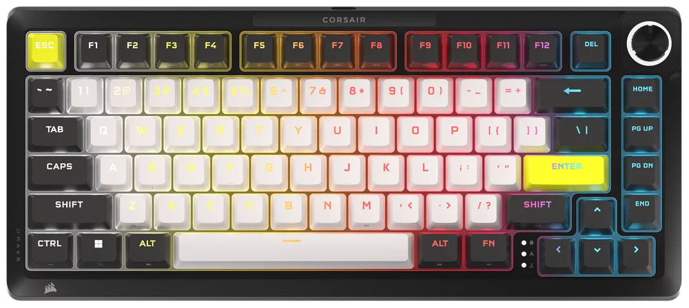
GETTING TO KNOW YOUR KEYBOARD
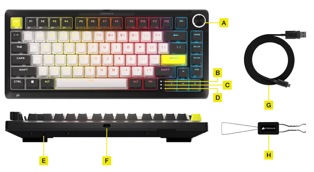
- MULTI-FUNCTION ROTARY DIAL
- WINDOWS LOCK INDICATOR
- CAPS LOCK INDICATOR
- SCROLL LOCK INDICATOR
- WIN/MAC SWITCH
- USB TYPE-C PORT
- USB TYPE-C TO TYPE-A CABLE
- 2-IN-1 KEYSWITCH/KEYCAP PULLER
OPTIONAL- ADD-ON MODULES:
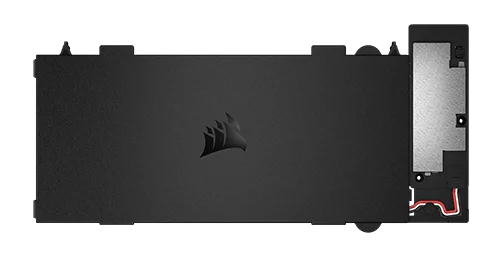
- Wireless Module
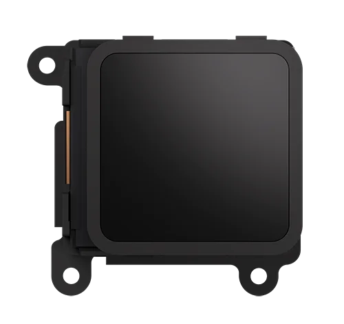
- LCD Module
HOW TO INSTALL THE WIRELESS MODULE
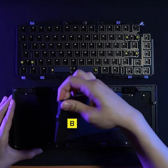
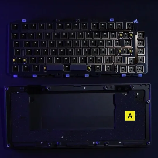
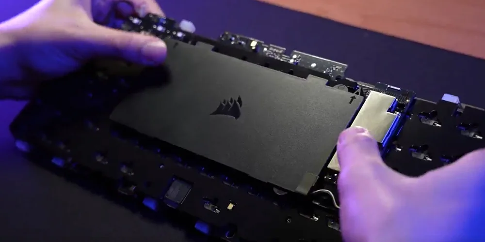
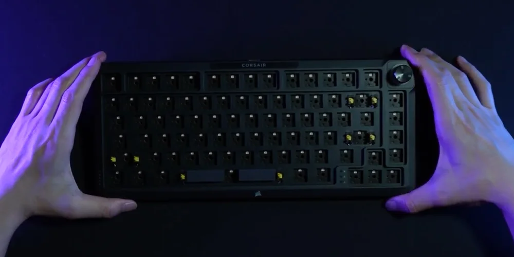
1. With the keyboard open, remove all of the internal components except for the bottom layers with the wireless battery cutout.
NOTE: There is a rubber pad (B) in wired model, please remove (B), only leaving battery cut pad (A).
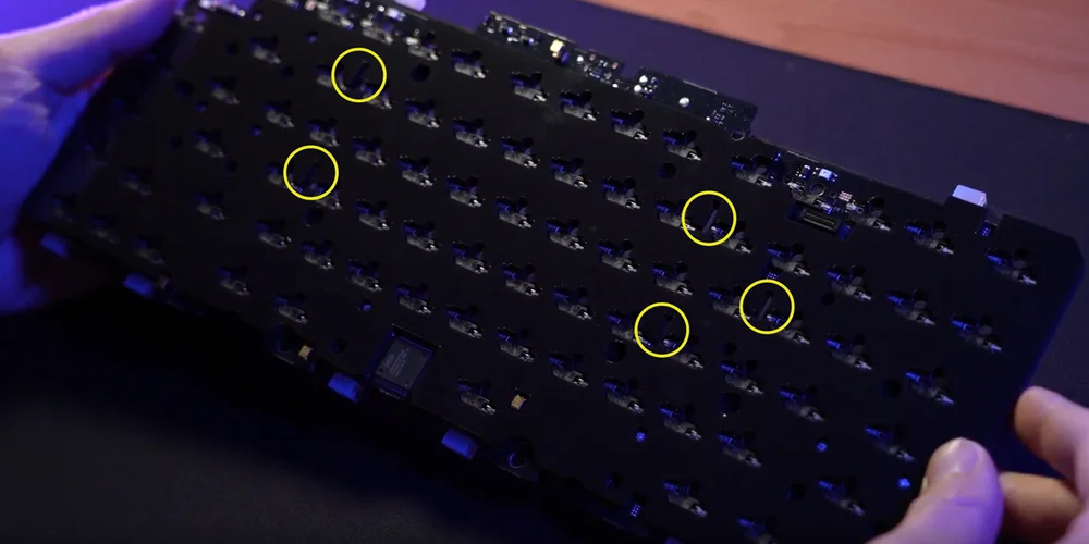
2. Install the wireless module by lining up the plastic pins with the corresponding slots on the rear of the socket foam. There are visual indicators to help guide this process. Once the plastic pins are lined up, apply some pressure to the four corners of the module until they click into place.
(1)
(2)
(3)
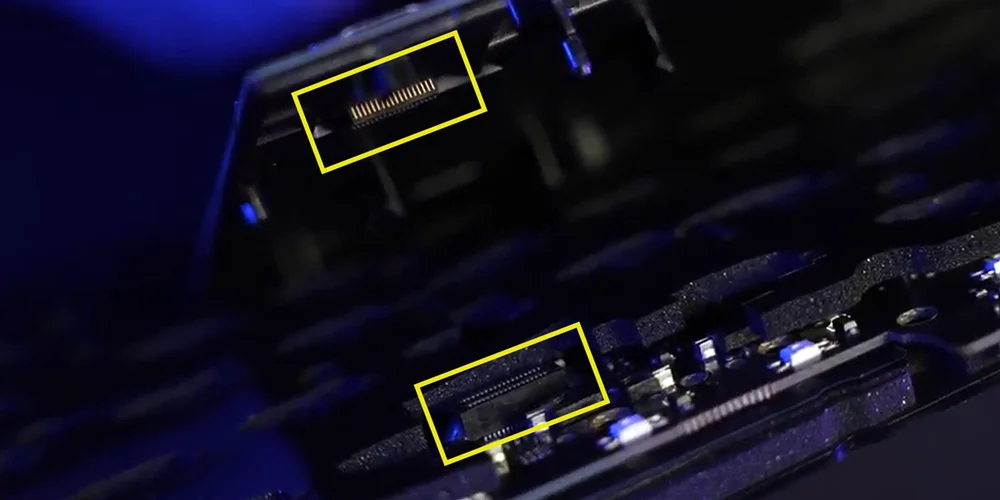
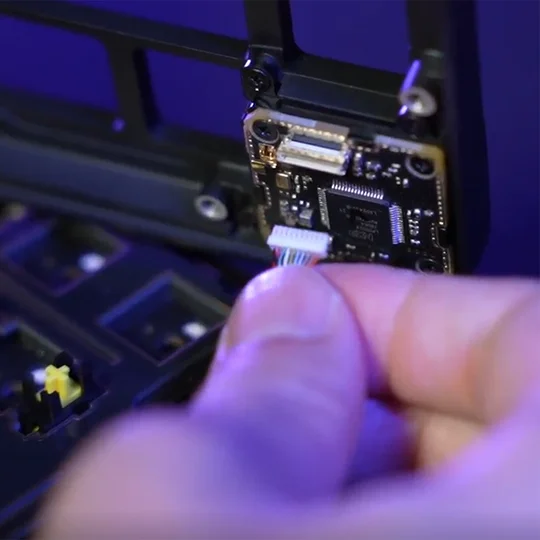
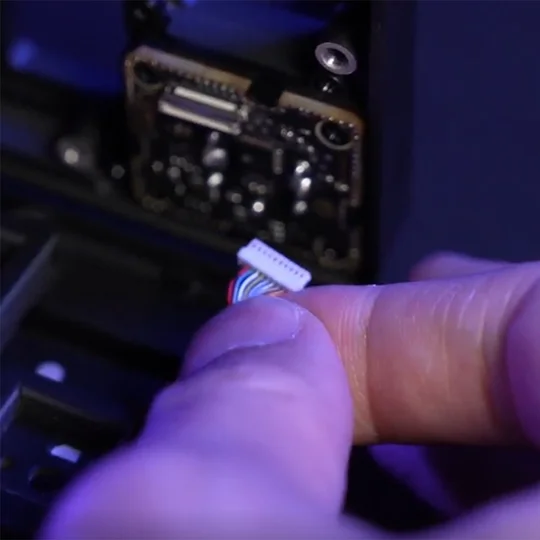
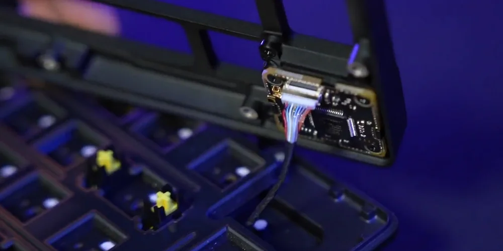
NOTE:
When connecting the Wireless Module to the PCB, please make sure these two connectors are fully seated. (Pic 1)
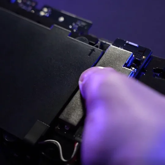
You can do this by gently pushing on the silver part of the wireless module (Pic 2) until you hear a click.
If you do not hear a click, stop pressing and return to Step 2 to make sure all plastic pins are aligned before pushing on the silver part again.
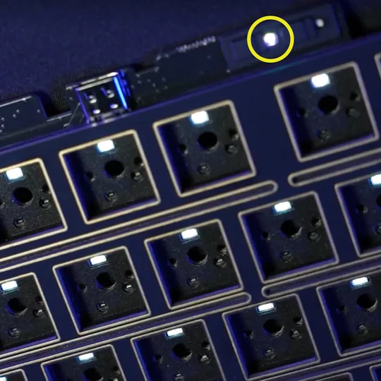
When the Wireless Module has been successfully installed, a white LED will turn on when the keyboard is powered. (Pic 3)
(1)
(2)
(3)
3. Replace the plastic forehead piece with the ‘CORSAIR’ wordmark  with the new plastic button covers included with the wireless module.
The correct installation order from left to right should be:
a. Power On/Off
b. CORSAIR wordmark
c. SLIPSTREAM 2.4GHz button
d. Bluetooth® button
HOW TO ENABLE WIRELESS CONNECTIVITY
-
With the Wireless Module installed, slide the power switch to the ON position to turn on the keyboard.
-
Press the Wireless button to switch to SLIPSTREAM Wireless 2.4GHz mode.
Power Switch Slid to ON / Wireless Button Pressed
Hold to begin SLIPSTREAM pairing.
-
Press the BT button to change to Bluetooth mode.
Hold to begin Bluetooth pairing.
Power Switch Slid to ON/ BT Button Pressed
HOW TO INSTALL THE LCD MODULE
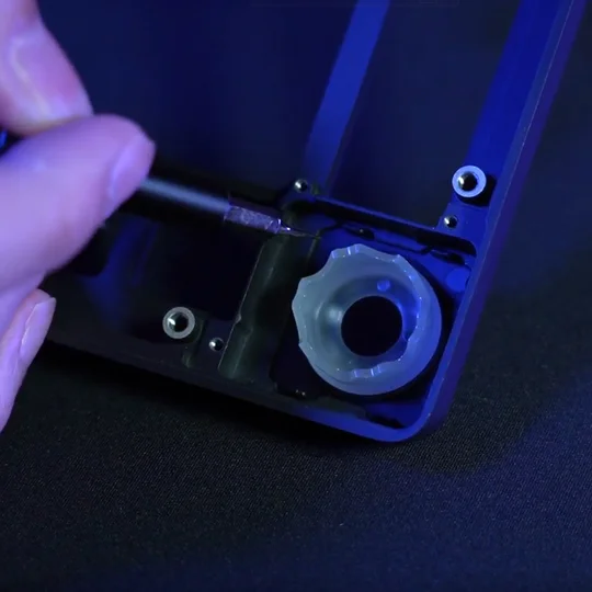
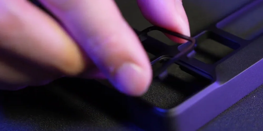
1. Remove the rotary dial module.
- Flip the kit upside down and remove the housing screws.
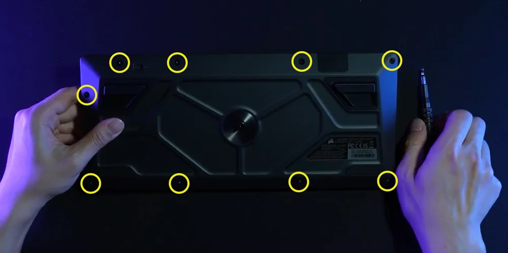
- Once the screws are removed, carefully flip it back over while holding the housing together to prevent any components from falling apart.
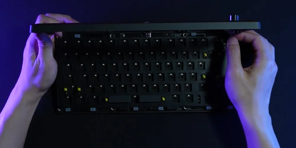
- Pull off the dial.
- Carefully lift the top housing upwards. Disconnect the ribbon cable from the housing.
(1)
(2)
(3)
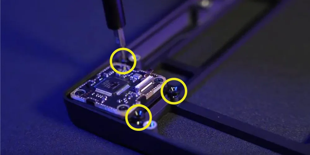
- Remove the three screws securing the rotary dial module.
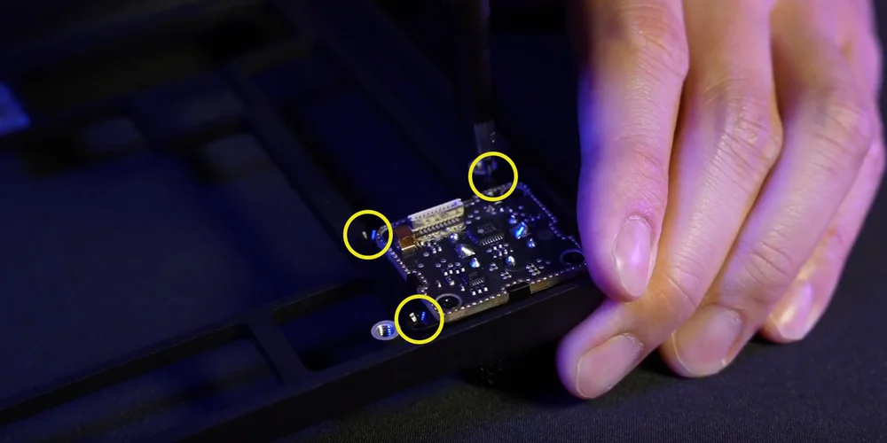
- Fully remove the dial module and store it in a safe place.
(1)
(2)
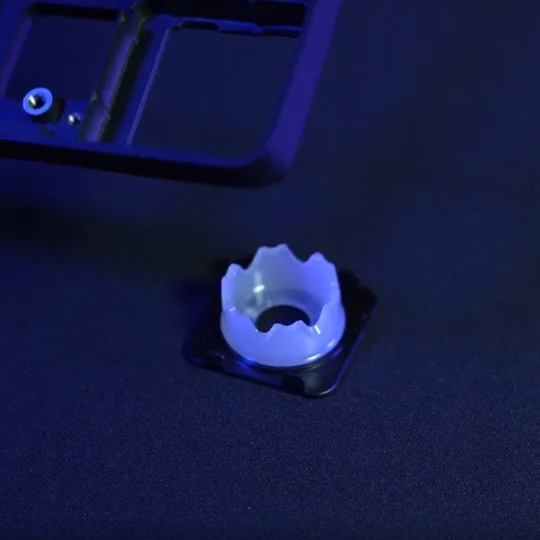
2. Install LCD Module
- Install the ring onto the upward-facing housing. (Backward-facing will not work.)
- Flip LCD to the back and secure it with three screws.
- Reattach the ribbon cable to the top housing.
TECHNICAL SPECIFICATIONS
| FEATURE | DESCRIPTION |
| Form Factor | 75% |
| Top cover | Full Aluminium |
| Bottom | Full Aluminium |
|
Colorway |
Eclipse |
|
Sound absorbing foam (Top to Bottom) |
8 layers
|
| Switch Plate | FR4 (with silicone gaskets) |
| Backlighting | Individually LED lit and per-key programmable |
| LED Color | RGB |
| Keycaps | PBT double shot |
| Keyswitches |
CORSAIR MGX Hyperdrive magnetic pre-lubricated keyswitches, 30 - 55g actuation force, 0.1-4.0mm* actuation distance (in 0.1mm steps), 4.1mm total travel, guaranteed for 150 million keystrokes * For optimal accuracy the recommended range is 0.3mm-3.6mm. Setting the actuation outside the recommended range may result in higher sensitivity and affect consistency |
| Connectivity | USB Type-A |
| Matrix | Full key rollover (NKRO) with 100% anti-ghosting |
| USB Report Rate | Up to 8,000Hz hyper-polling |
| On-Board Profiles | Default: 1, can be up to 5 profiles |
| Media Control | FN shortcuts/Rotary dial |
| FlashTap (SOCD) |
FN + Right Shift iCUE UI CORSAIR WEB HUB |
| Brightness Control | FN shortcuts/Rotary dial |
| Adjustable Height | Yes |
| Plug and Play Operation | Yes |
| Console Compatibility | Xbox One, Xbox Series X|S, PlayStation 4, 5 |
| Cable | 1.8m/6ft, USB Type-C to Type-A, detachable, black, tangle-free rubber |
| Dimensions | 332(L) x 145(W) x 50(H) mm |
| Weight | 1.3kg |
| Warranty | Two years – Local country regulations are applicable |
OPTIONAL- ADD-ON MODULES
WIRELESS MODULE
| Dimensions | 188.8(L) x 90.7(W) x 11.9(H) mm |
| Weight | 111.9g |
| Warranty | Two years – Local country regulations are applicable |
| Battery Specifications | Type: Built-in lithium-ion polymer, rechargeable |
|
Battery Life:
|
|
| Charging: Charges via USB around 5 hours, depending on battery drain and usage | |
| Configuration: 1S1P | |
| Quantity: 1 | |
| Cells: 1 | |
| Model#: 2670155 | |
| Capacity: 4170mAh | |
| Dimensions: 159(L) x 70.3(W) x 3.0(H) mm | |
| Dimensions (with cable): 199(L) x 70.3(W) x 3.0(H) mm | |
| Weight: 71g | |
| Lithium Content: 1.251g | |
| HAZMAT UN #: UN3481 | |
| HAZMAT Description: PI967 - Contained in equipment |
LCD MODULE
| Size | 1.3 inch |
| Resolution | 240x240 resolution |
| Dimensions | 33.77 (L) x 36.26 (W) x 15.8(H) mm |
| Weight | 13.5g |
| Picture Upload Specs |
|
| Warranty | Two years – Local country regulations are applicable |
CORSAIR MGX HYPERDRIVE MAGNETIC KEYSWITCHES
CORSAIR MGX Hyperdrive magnetic keyswitches offer a super smooth, quieter, and wobble free typing feel that can be programmed to detect the keystroke at anywhere from a 0.1mm to 4.0mm* actuation distance putting you in full control over how sensitive each key press is to ensure the gaming and typing experience is suited to you.
* For optimal accuracy the recommended range is 0.3mm-3.6mm. Setting the actuation outside the recommended range may result in higher sensitivity and affect consistency.

AXON HYPER-PROCESSING TECHNOLOGY
CORSAIR AXON delivers a powerful and responsive keyboard experience with:
- Hyper-fast keystroke detection and processing.
- Up to 8,000Hz hyper-polling (adjustable in iCUE and CORSAIR WEB HUB device settings).
- Up to 20-layer onboard lighting effects (programmable in iCUE per profile).

SETTING UP YOUR KEYBOARD
| Windows® PC | Apple Mac® |
Microsoft Xbox One* Microsoft Xbox Series X | S* |
Sony PlayStation 4** Sony PlayStation 5** |
**See Connecting to Sony PlayStation section.
CONNECTING TO SONY PLAYSTATION
The keyboard also has a special mode to support Sony PlayStation 4 and 5 that can be activated via shortcut.
| SHORTCUT | FUNCTION | INDICATION |
| FN+ |
Switch to PlayStation mode | |
| FN+ |
Switch back to standard mode |
NOTE: Available functions may be limited depending on gaming console support and application.
CONNECTING VIA WIRELESS MODE (Available only with the Wireless Module installed)
When the USB cable is plugged in, the device automatically switches to USB mode.
When the USB cable is unplugged, the device switches to the last used wireless mode.
| FUNCTION NAME | BUTTON | FUNCTION | INDICATOR | INDICATION/STATUS |
| USB Cable | N/A | Automatically switches to USB mode when the cable is plugged in. | Wireless button |
Solid Yellow |
| SLIPSTREAM Wireless | Wireless button |
Press wireless button to switch to SLIPSTREAM wireless 2.4GHz mode | Wireless button |
Solid White: Connected Pulsing White: Not connected |
| Hold wireless button to begin pairing* | Rapidly blink white for 120s during pairing | |||
| Bluetooth 1 | Bluetooth button |
|
Bluetooth button |
Solid Blue: Connected. Pulsing Blue: Not connected
Rapidly blinks blue for 120s during pairing |
| Bluetooth 2 | Bluetooth button |
|||
| Bluetooth 3 | Bluetooth button |
*SLIPSTREAM Wireless pairing: You can also pair the dongle with the keyboard via iCUE.
Steps: Find Pair button under dongle page circled in yellow.
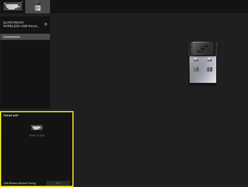
*To complete pairing to a SLIPSTREAM wireless adapter, initiate adapter pairing in iCUE device settings.
CHARGING & BATTERY LIFE

| FUNCTION NAME | BUTTON | FUNCTION | INDICATION |
| Battery Check | FN + Esc |
Press FN + Esc to show the battery level color/effect on the Esc key for 3 seconds. |
Critical: Pulses red (ongoing event) Low: Blinks red Medium: Blinks amber High: Blinks green Fully charged: Solid green *When charging with the USB cable plugged in, the indicator will keep pulsing green until fully charged. Indicator will turn solid green when fully charged. |
OPERATING MODES
The keyboard features three operating modes:
- Hardware (HW) Mode – When iCUE is not running or the keyboard is connected to a device that does not support iCUE, the keyboard operates in hardware mode which uses profiles and settings saved to the onboard storage.
- Software (SW) Mode – When iCUE is running on a PC or Mac, the keyboard operates in software mode and is controlled by iCUE.
- Download iCUE from corsair.com/downloads and install on a Windows PC or Apple Mac to connect all your CORSAIR iCUE compatible products together in a single interface, giving you complete control of everything from lighting to powerful macros.

- Download iCUE from corsair.com/downloads and install on a Windows PC or Apple Mac to connect all your CORSAIR iCUE compatible products together in a single interface, giving you complete control of everything from lighting to powerful macros.
- Web-based mode – When iCUE is not running, go to CORSAIR Web Hub link https://corsair.com/web-hub, the keyboard operates in Web-based mode, using profiles and settings saved to onboard storage.

| FUNCTION | HARDWARE MODE | WEB-BASED MODE | SOFTWARE MODE |
| Storage & Profiles | 1 profile up to 5 profiles | 5 profiles | Unlimited |
| Create New Profiles | Create in iCUE | Create in CORSAIR WEB HUB | Create in iCUE |
| Create Lighting Effects | Create in iCUE | Create in CORSAIR WEB HUB | Create in iCUE |
| Create Key Assignments | Create in iCUE | Create in CORSAIR WEB HUB | Create in iCUE |
| Maximum Lighting Layers | 20 | 5 |
Unlimited (wired mode) 20 (wireless mode) |
HARDWARE OVERVIEW
FN SHORTCUTS LIGHTING INDICATOR
When pressing FN key, all lighting will momentarily turn OFF, except for keys that have secondary functions and macros assigned to them. Those keys will have backlighting turned ON.
- The default color will be white.
- Users can customize the color indication in iCUE.
Color indication for the profile currently in use will take priority over FN Shortcut lighting.
HARDWARE ACTUATION SETTING (TABLE A)
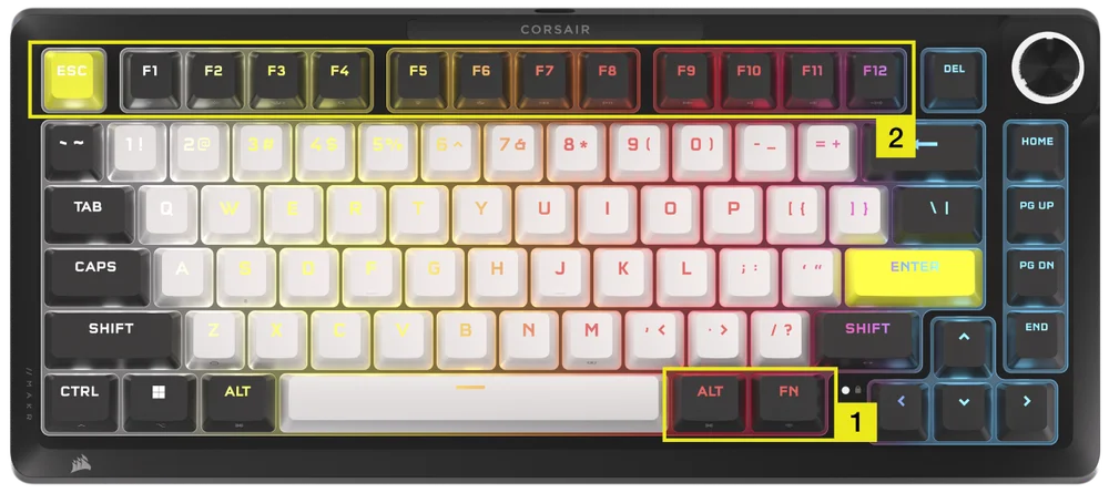
Please make sure both iCUE and CORSAIR WEB HUB are turned off before performing the hardware actuation setup.
- Hold FN + Right Alt for 2 seconds until keyboard lighting turns off except for ESC, F1-F12, 4-0, -_ and =+ keys.
- Press one of the lit-up keys from ESC and F1-F12 to set all keys to that actuation distance.
- All analog keys (except ESC, F1-F12, 4-0, -_ and =+ keys but include the selected ones) light up with breath (selected color).
- Press the same sensitivity key to revert to current Hardware mode setting.
| Key | ESC | F1 | F2 | F3 | F4 | F5 | F6 |
| Actuation Distance (mm) | 0.8 | 1.0 | 1.2 | 1.4 | 1.6 | 1.8 | 2.0 (Default) |
| Color | White | Orange | Amber | Yellow | Green | Cyan | Capri |
| Key | F7 | F8 | F9 | F10 | F11 | F12 |
| Actuation Distance (mm) | 2.2 | 2.4 | 2.6 | 2.8 | 3.0 | 3.2 |
| Color | Blue | Indigo | Purple | Violet | Magenta | Red |
- Press FN + Right Alt to exit and try out your new settings.
| Gaming (Improved Response) | Multi-use (Balanced) | Typing (Improved Accuracy) |
| 1.0mm | 2.0mm (Default) | 3.0mm |
In software mode with iCUE you get access to even more powerful control to further fine-tine actuation settings in 0.1mm increments from the full 0.1mm to 4.0mm* range which can be saved per profile or assign actions to a secondary actuation for rapid fire combos or advanced walk-run movement.
*For optimal accuracy the recommended range is 0.3mm-3.6mm. Setting the actuation outside the recommended range may result in higher sensitivity and affect consistency.
HARDWARE RAPID TRIGGER ACTUATION SETTING (TABLE B)
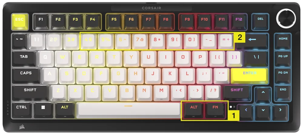
Please make sure both iCUE and CORSAIR WEB HUB are turned off before performing the hardware actuation setup.
- Hold FN + Right Alt for 2 seconds until keyboard lighting turns off except for ESC, F1-F12, 4-0 , -_ and =+ keys.
- Press one of the lit-up keys from 4 -0, -_ and =+ keys for Rapid Trigger Actuation Point settings to apply to all keys.
- Press the same sensitivity key to revert to current Hardware mode setting.
| Key | 4 | 5 | 6 | 7 | 8 | 9 | 0 | -_ | =+ |
| Actuation Distance (mm) | 0.4 | 0.5 | 0.6 |
0.7 |
0.8 | 0.9 | 1.0 (Defalt) | 1.1 | 1.2 |
| Color | Amber | Yellow | Green | Cyan | Capri | Blue | Purple | Magenta | Red |
- Press FN + Right Alt to exit and try out your new settings.
HARDWARE CALIBRATION
For special cases such that the actuation points are no longer in place, you may utilize this unique Hardware calibration tool.
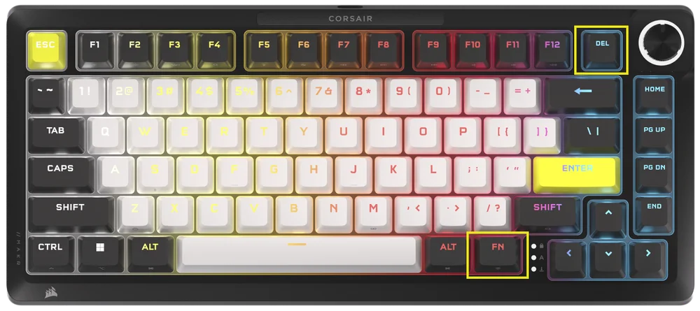
Please make sure both iCUE and Corsair Web Hub are turned off before performing the hardware actuation setup.
-
Hold FN + Delete for 2 seconds to enter calibration mode
-
All keys light up with Solid White, FN key plays SOLID green
-
Hold any keys that you want to calibrate
a. FN key and the hold key play solid red while calibrating
b. FN key and the hold key play solid blue when calibration is finished
-
Release the key that you want to calibrate
a. FN key and the hold key play solid green when calibration is completed
- Hold FN for 2 seconds to exit calibration mode and reset device
ROTARY DIAL FUNCTION
Dial modes are cycled through via holding the dial for 2 seconds.
The Rotary Dial ring will display the color corresponding to the current dial mode. Current dial mode does not change upon power cycling.
| MODE | LED COLOR | LED INDICATION | TWIST | PRESS |
| Volume | White | Solid |
|
Mute/Unmute |
| Media Control | Blue | Solid |
|
Play/Pause |
| Lighting | Cyan | LEDs light-up based on brightness % |
|
Turn On (100%)/Off (0%) |
| Macro Recording | Red |
Idle State: Breathe Red Recording State: Blink Red Finish Recording: Rapidly blink red Clearing State: Rapidly blink red |
N/A | Start macro recording |
| Track Jogging | Green | Solid |
Windows:
Mac OS Apple Music:
Mac OS Spotify:
|
N/A |
| Switch application | Lime | Solid |
|
|
| Vertical scrolling | Orange | Solid |
|
Ctrl+ END |
| Horizontal scrolling | Yellow | Solid |
|
Ctrl+ END |
| Zoom | Purple | Solid |
|
Restore to default zoom action |
| iCUE Custom Actions | User defined | Solid |
|
Action 1 |
STANDARD SHORTCUTS
All functions below assume FN key is being held and action is activated upon press unless otherwise noted.
| KEY | FUNCTION |
SCREEN INDICATOR (If LCD is installed) |
REMARKS |
| FN + ESC | Battery Check | No | Does nothing without wireless module. |
| FN + F1 | Reduce screen brightness | Yes | |
| FN + F2 | Increase screen brightness | Yes | |
| FN + F3 | Toggle Task View for Windows | No | macOS: Mission Control |
| FN + F4 | Launch File Explorer | No | macOS: Spotlight search |
| FN + F5 | Decrease keyboard LED brightness in 10% increments | Yes | macOS: Dictation/Siri |
| FN + F6 |
Increase keyboard LED brightness in 10% increments |
Yes | macOS: Do not Disturb |
| FN + F7 | Previous media track | Yes | |
| FN + F8 | Play/Pause media track | Yes | |
| FN + F9 | Next media track | Yes | |
| FN + F10 | Mute/Unmute volume | Yes | |
| FN + F11 | Decrease volume in 2% increments | Yes | |
| FN + F12 | Increase volume in 2% increments | Yes | |
| FN + S | Toggle Scroll Lock on and off | Yes | macOS: No function |
| FN + Z | Cycle profiles | Yes | Self indicates on key color of profile with solid color 5 sec unless overriden |
| FN + C | Cycle through onboard lighting effects | Yes | Hold 2 seconds to reset to onboard effect |
| FN + V | Cycle lighting effect direction settings | Yes | |
| FN + B | Cycle through lighting effect speed settings | Yes | |
| FN + M | Enter macro recording mode | Yes | Need to hold 2 seconds |
| FN + Win | Toggle win lock on and off | Yes | |
| FN + Right Shift | Toggle FlashTap on/off | No | |
| FN + Left | Move left in screen UI | No | Does nothing without screen module |
| FN + Right | Move right in screen UI | No | |
| FN + ENTER | Activate screen element | No |
MACRO RECORDING
- Enter macro recording mode
- Hold FN + M key for 2 seconds or hold rotary dial in macro recording mode (LED color showing red)
- Indicator M key will breathe red
- Dial or screen if present should be playing their macro recording indications as well
- Press any series of standard keys to begin recording
- This includes shortcuts such as FN + key commands as possible (based on firmware/software limitations) for example FN + S is recorded as Scroll lock
- Only standard keyboard functions can be recorded and not specialty or onboard functions like
- Mouse cursor
- Profile
- Backlighting effects
- Brightness
- Media
- Volume
- Win lock
- Only standard keyboard functions can be recorded and not specialty or onboard functions like
- Delays are also recorded
- Indication: Indicator M key (and rotary dial if present) blink red
- This includes shortcuts such as FN + key commands as possible (based on firmware/software limitations) for example FN + S is recorded as Scroll lock
- Press FN + M key for 2 seconds or press rotary dial to stop recording and prepare macro to be saved or cleared
- Pressing this more than once has no added function
- Indication: Indicator M key (and rotary dial if present) rapidly blink red
- Press any key, FN + key
- If keys were recorded: Pressing that key or combination saves the macro
- If no keys were recorded: Pressing that key or combination clears any macro or function saved
- If there is a firmware shortcut normally bound to that combination, it is restored
- Except cannot record over these keys or key combinations:
- FN
- FN + M
- FN + ESC
- FN + Windows
- Indication: Key combination that the macro has been assigned to rapidly blinks red
- NOTE: Red indication color is default, user can change.
FLASHTAP (SOCD)
FlashTap is a revolutionary technology that puts the player in complete control of their movement keys, left and right in particular, optimizing SOCD behavior across every game and genre.
FlashTap will be disabled by default in HW mode and iCUE and CORSAIR WEB HUB.
HW mode behavior
- Non-profile dependent, enable via shortcuts: FN + Right SHIFT
- Supports key A + D, last priority only
- Indication: A & D stay solid amber when FlashTap is on (overrides existing lighting)
iCUE & Corsair Web Hub behavior (Please refer more details to iCUE & CORSAIR WEB HUB section)
- Supports advanced feature such as mode selection and key remapping
- Can be configured with profile
- Mode selection details
|
Last priority (default when on) |
Always output last direction and bypass the other one |
| Neutral | No output when both directions are triggered at the same time |
| First Priority | Always output first direction and bypass the other one |
SOFTWARE OVERVIEW
CORSAIR WEB HUB
CORSAIR WEB HUB is the lightweight, web-based utility to customize your MAKR PRO 75 keyboard. It’s powerful, easy-to-use, and doesn’t require any additional software installation. Try it here: https://corsair.com/web-hub

When you first open CORSAIR WEB HUB, you will see a device name for MAKR PRO 75. Clicking it will present options to start programming for:
- Lighting Effects
- Key Assignments
- Multi-Action keys
- Key Actuations
- Rotary Dial
- FlashTap
- Key Calibration
LIGHTING EFFECTS
The Lighting Effects tab allows you to program lighting effects.
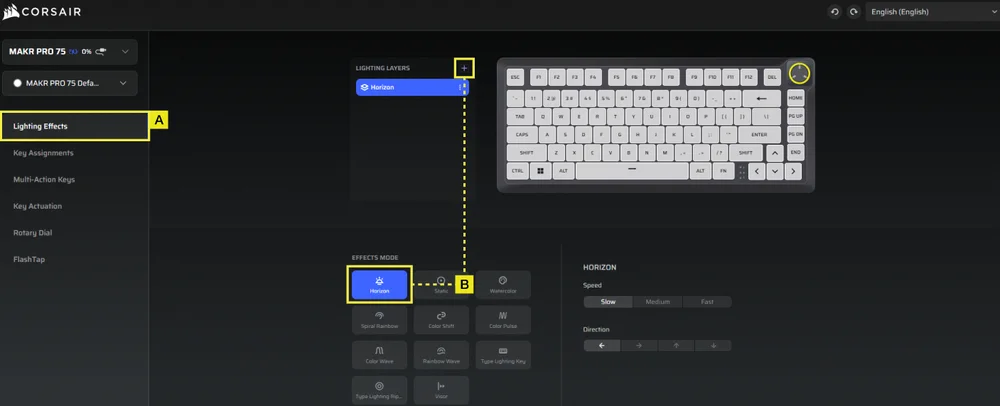
A. Choose Lighting Effects tab.
B. Click + to set lighting layers to your liking.
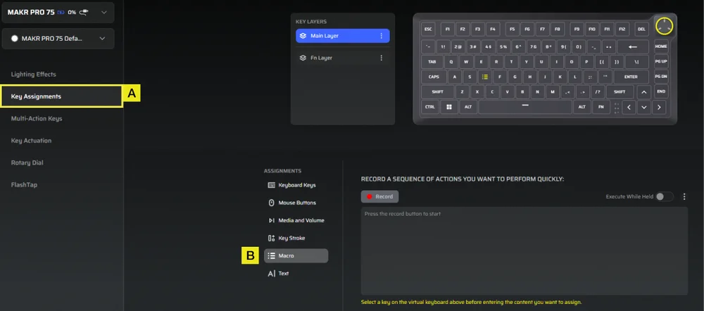
KEY ASSIGNMENTS
The Key Assignments tab allows you to easily remap keys or assign new functions to keys.
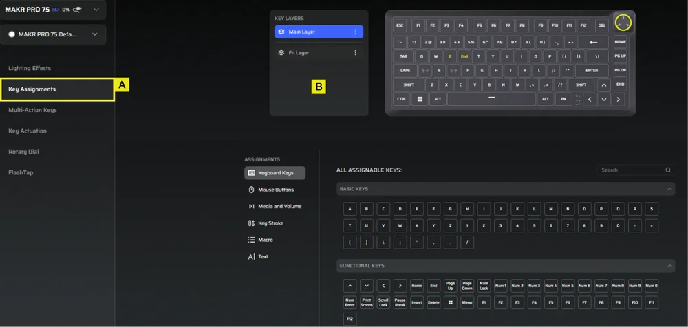
A. Choose Key Assignments tab.
B. Select the keys in either the Main layer or the FN layer, and assign them to any function listed in the menu.
MULTI-ACTION KEYS
The Multi-Action Keys tab allows you to enable secondary actuation points, enabling advanced 2-in-1 keypress combinations.
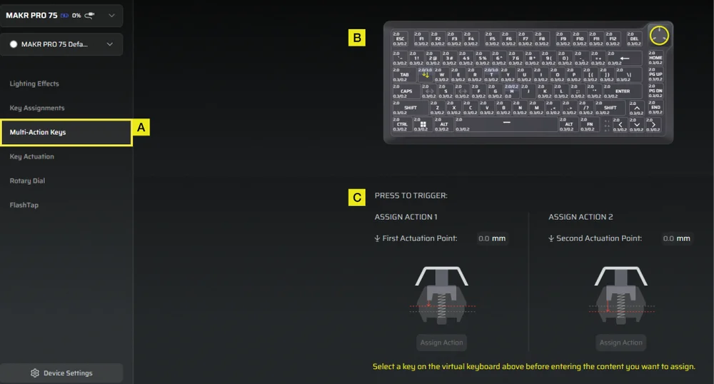
A. Choose Multi-Action Keys tab.
B. Select keys that you want to apply this setting on.
C. Adjust the actuation points for both Action 1 and Action 2. Then, open the Assign Action panel for each to choose your preferred functions.
KEY ACTUATIONS
The Key Actuations tab is where you can adjust the actuation point. The default setting is 2.0mm and you can adjust from a range between 0.1mm–4.0*mm. Here you will also find Rapid Trigger setting which allow for dynamically change actuation and reset points.
*For optimal accuracy the recommended range is 0.3mm-3.6mm. Setting the actuation outside the recommended range may result in higher sensitivity and affect consistency.
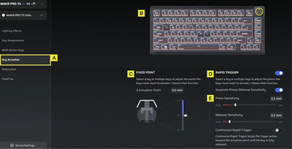
A. Choose Key Actuation tab.
B. Select keys to adjust their actuation behavior.
C. Under Fixed Point, set the Actuation Point.
D. Toggle on Rapid Trigger (Default is off) to adjust the sensitivity for press and release points independently.
E. Use the sliders to fine-tune Press Sensitivity and Release Sensitivity, or enable Continuous Rapid Trigger for faster repeated inputs.
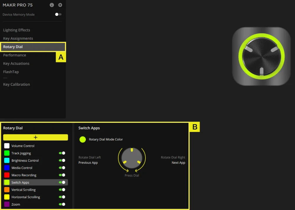
ROTARY DIAL
The Rotary Dial tab allows you to choose which mode you want.
Default setting is with all modes on.

A. Choose Rotary Dial tab.
B. Pick the dial mode.
FLASHTAP (SOCD)
The FlashTap (SOCD) tab allows you to choose between three different settings and assign specific key pairs to support FlashTap.
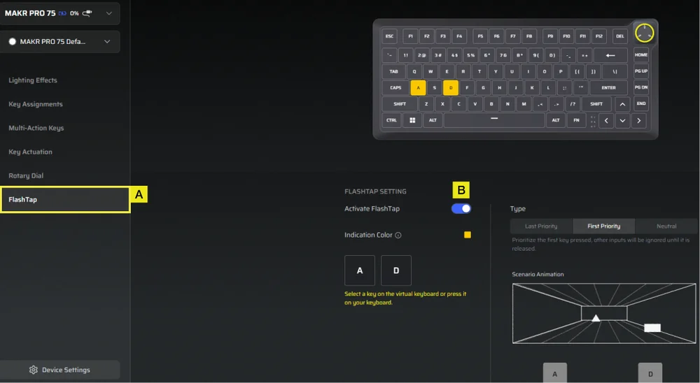
A. Choose FlashTap tab.
B. Toggle FlashTap on (Default is off), then choose your preferred setting and assign the two keys as desired.
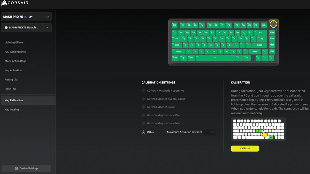
KEY CALIBRATION
The Key Calibration tab allows you to calibrate the magnetic switches listed in the Calibration Settings panel.
(See instruction video: https://youtu.be/pVrzB89FWBw)
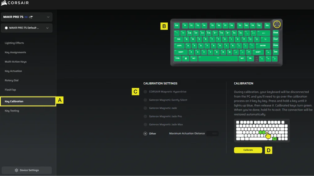
A. Choose Key Calibration tab.
B. Select the keys you want to calibrate.
C. The switch types in the “Calibration Settings” will highlight for selection. Choose the switch type installed on those keys.
D. Click the Calibrate button.
E. The keyboard will temporarily disconnect from the PC, which will bring you to the portal page. During this process, follow the steps below to complete calibration:
- Hold a key until that key and the FN key turn solid blue, then release the key.
- The FN key and the hold key will turn solid green once calibration is complete.
- Hold the FN key for 2 seconds to exit calibration mode and reset device- you will see the boot-up animation.
- After the calibration process completes, you will be returned to the calibration page.
DEVICE SETTINGS
The Device Settings tab allows you to change advanced settings, adjust the polling rate, and update the firmware.
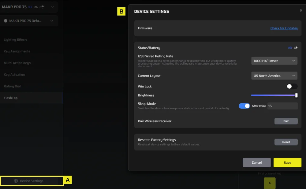
A. Click the Device Settings tab.
B. Change the advanced settings (Polling rate, brightness…etc).
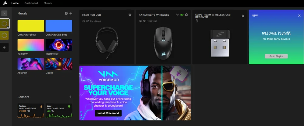
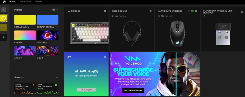
iCUE HOME AND DEVICE SCREEN
When you first open iCUE, you will see a new device tile for MAKR PRO 75. Clicking the device tile will present options to start programming for:
- Lighting Effects
- Key Assignments
- Rotary Dial
- Performance
- Key Actuations
- FlashTap
- Key Calibration
If you see an update notification in the iCUE window, please click to update firmware to the latest version.
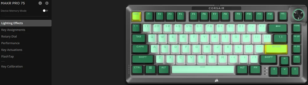
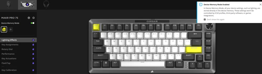
DEVICE MEMORY MODE
Before you start programming, note that every iCUE system profile has two sets of settings - Software Mode and Device Memory Mode.
The Device Memory mode menu allows you to assign functions which can be saved to the keyboard’s onboard memory and plays when in hardware mode.
| FUNCTION |
DEVICE MEMORY MODE
|
SOFTWARE MODE
|
| Storage & Profiles | 1MB for up 5 profiles | Unlimited |
| Features |
|
|
| How to Save |
Manual Save
|
Automatically |
| Maximum Lighting Layers | 20 |
Unlimited |


LIGHTING EFFECTS
The Lighting Effects tab allows you to program lighting effects.
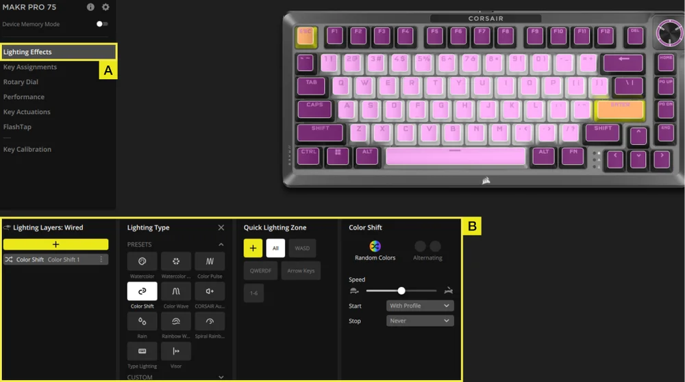
A. Choose Lighting Effects tab.
B. Under lighting layers click [ + ] to set lighting to your liking.
KEY ASSIGNMENTS
The Key Assignments tab allows you to easily remap keys or assign new functions to keys.
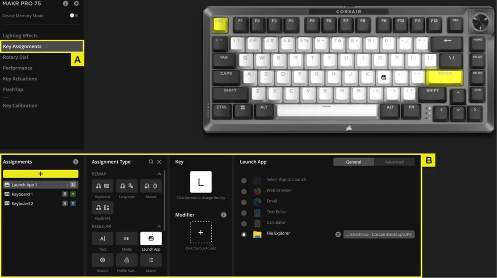
A. Choose Key Assignments tab.
B. Under Assignments click [ + ] to remap keys or assign new functions.
ROTARY DIAL
The Rotary Dial tab allows you to choose which mode you want.
Default setting is with all modes on.
A. Choose Rotary Dial tab.
B. Toggle your desired modes on and off.
PERFORMANCE
The Performance tab allows you to enable/disable shortcuts and customize indicator colors.
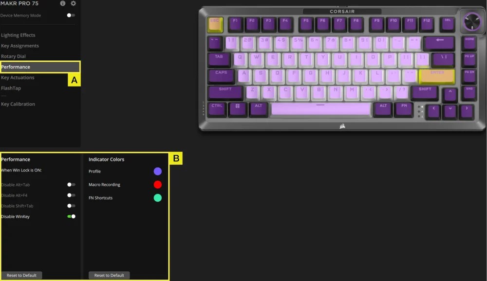
A. Choose Performance tab.
B. Enable/disable shortcuts or customize indicator colors to your liking.
KEY ACTUATIONS
The Key Actuations tab is where you can adjust the actuation point. The default setting is 2.0mm and you can adjust from a range between 0.1mm–4.0*mm. Here you will also find a setting to enable secondary actuation points which allow for advanced 2-in-1 keypress combos and Rapid Trigger setting which allow for dynamically change actuation and reset points.
*For optimal accuracy the recommended range is 0.3mm-3.6mm. Setting the actuation outside the recommended range may result in higher sensitivity and affect consistency.
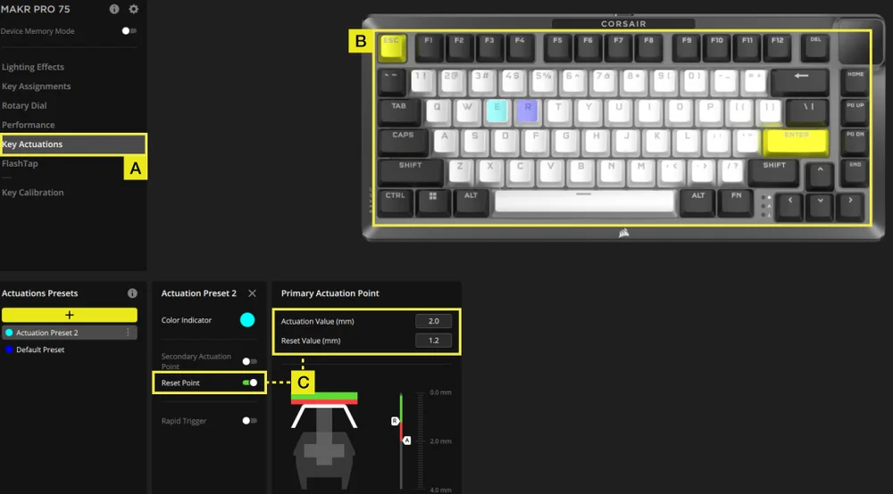
A. Choose Key Actuation tab.
B. Select keys that you want to apply this setting on.
C. Under Actuations Presets click [ + ] to adjust actuation value in 0.1mm steps (Default:2mm), toggling reset point on (Default is off) to adjust reset value in 0.1mm steps (Default:1.9mm).
TWO ACTIONS SETTING
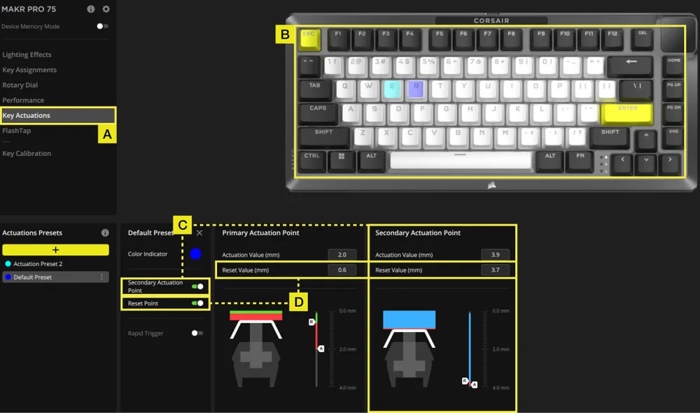
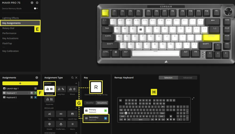
A. Choose Key Actuation tab.
B. Select keys that you want to apply this setting on.
C. Toggle Second Actuation Point on (Default is off) to adjust secondary actuation value in 0.1mm steps (Default:3.5mm).
D. Toggle reset point on (Default is off) to adjust reset value in 0.1mm steps (Primary actuation default:1.9mm; secondary actuation default:3.4mm).
E. Go to Key Assignments tab.
F. In the assignment type menu, select remap .
G. Select the key that has two assigned actions, then choose secondary under actuation tab.
H. Choose the key that contains the action you want to assign.
RAPID TRIGGER SETTING
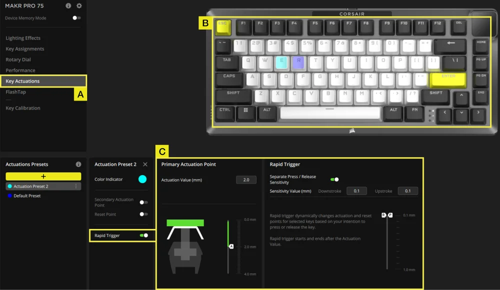
A. Choose Key Actuation tab.
B. Select keys that you want to apply this setting on .
C. Toggle Rapid Trigger on (Default is off). Toggle Separate Press/Release sensitivity on (Default is off) to adjust downstroke & upstroke value (Default:0.1mm)
Here is an example of how you would configure actuation points to best handle various scenarios. We highly recommend users to tweak and experiment to find the best setup to suit their preferences.
| USAGE | ACTUATION VALUE | BENEFIT |
| Competitive gaming | 1.0mm | Enables faster and more responsive inputs. |
| General use | 2.0mm (Default) | A good middle ground between speed and accuracy. This is the default setting. |
| Typing | 3.0mm | Reduces the likelihood of accidental keypresses. |
FLASHTAP (SOCD)
The FlashTap (SOCD) tab allows you to choose between three different settings and assign specific key pairs to support FlashTap.
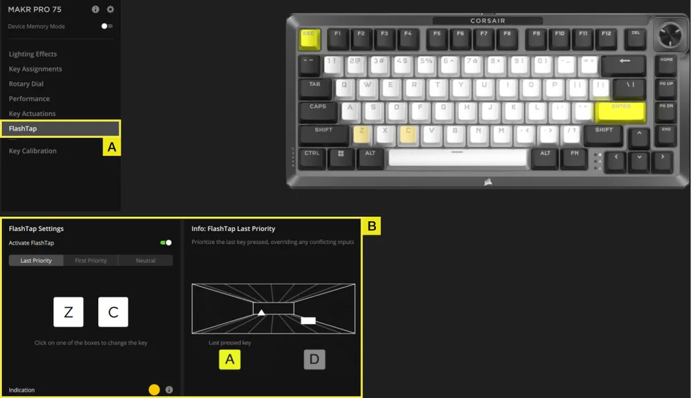
A. Choose FlashTap tab.
B. Toggle FlashTap on (Default is off), then choose your preferred setting and assign the two keys as desired.
KEY CALIBRATION
The Key Calibration tab allows you to calibrate the magnetic switches listed in the Calibration Settings panel.
(See instruction video: https://youtu.be/wbyFtZx3KEE)
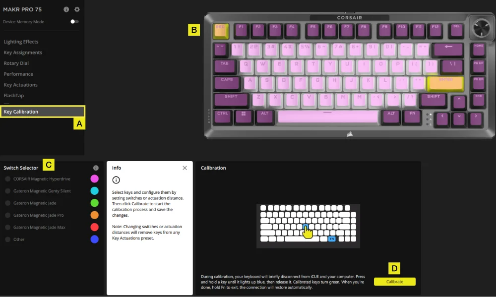
A. Choose Key Calibration tab.
B. Select the keys you want to calibrate.
C. The switch types in the Switch Selector will highlight for selection. Choose the switch type installed on those keys.
D. Click the Calibrate button.
E. The keyboard will temporarily disconnect from the PC, which will bring you to the portal page where the MAKR PRO 75 device panel will not be visible. Follow the steps below to complete calibration:
- Hold a key until that key and the FN key turn solid blue, then release the key.
- The FN key and the hold key will turn solid green once calibration is complete.
- Hold the FN key for 2 seconds to exit calibration mode and reset device- you will see the boot-up animation.
- After calibration is finished, the MAKR PRO 75 will reappear in the device panel.
DEVICE SETTINGS
The Device Settings tab allows you to change advanced settings, adjust the polling rate, and update the firmware.
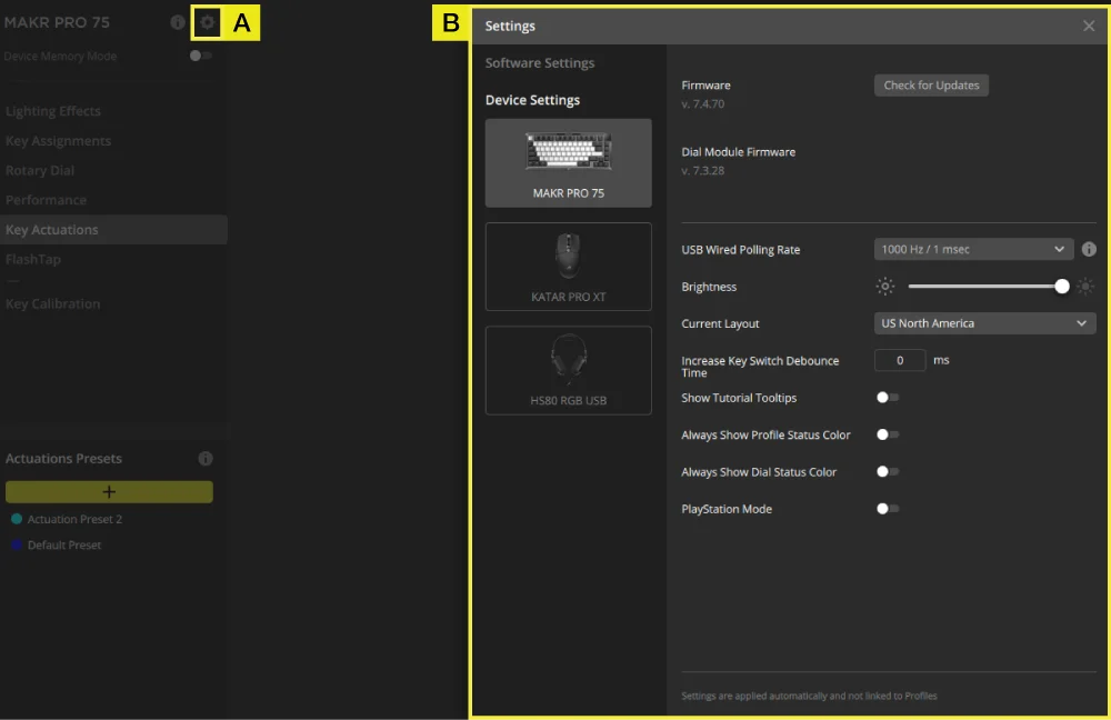
A. Click the setting icon.
B. Change the advanced settings (Polling rate, brightness…etc).
MACRO RECORDING
Can be programmed in iCUE and CORSAIR WEB HUB.
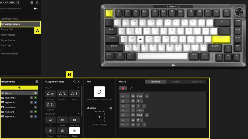
iCUE
CORSAIR WEB HUB
A. Choose Key Assignments tab.
B. Click assignment type Macro, starting Macro recording after remapping keys.
FACTORY RESET
Hold the ESC key while unplugging and plugging in the USB Type-C cable, then release the ESC key after two seconds. The keyboard will then be powered on, with factory default settings restored.
BATTERY REMOVAL INFORMATION

- Remove 2pcs screws from the PCBA
- Remove the PCBA from the battery holder
- Remove the battery cover
- Remove the battery from PCBA connecter
BATTERY INFORMATION
- M/N(型號): 2670155
- Capacity(電池容量): 3.7V, 4170mAh, 15.43Wh
- Scan QR code for battery details

FCC ID: 2AAFM-RGP0175 (Wireless module)
FCC ID: 2AAFM-RGP0146A (Dongle)
IC: 10954A-RGP0175 (Wireless module)
IC: 10954A-RGP0146 (Dongle)
M/N(型號): RGP0176
Rating(電壓電流): 5V
COPYRIGHT / LEGAL INFORMATION
KDB 996369 D03 OEM Manual rule sections:
2.2 List of applicable FCC rules
This module has been tested for compliance to FCC Part 15.247, 15.249
2.3 Summarize the specific operational use conditions
The module is evaluated for compliance to standalone portable RF exposure use condition. Any other usage conditions such as colocation with other transmitter(s) will need a separate reassessment through a class II permissive change application or new certification
2.4 Limited module procedures
Not applicable.
2.6 RF exposure considerations
This equipment complies with FCC portable radiation exposure limits set forth for an uncontrolled environment. Further RF exposure reduction can be achieved if the product can be kept as far as possible from the user body.
2.7 Antennas
The following antennas have been certified for use with this module; antennas of the same type with equal or lower gain may also be used with this module, except as described below.
| Antenna Manufacturer | Unictron Technologies Corp. |
| Antenna Model | CW801S |
| Antenna Type | Chip Antenna |
| Antenna Gain (dBi) | -4.07 |
| Antenna Connector | N/A |
2.8 Label and compliance information
The final end product must be labeled in a visible area with the following: “Contains FCC ID: 2AAFM-RGP0175. The grantee's FCC ID can be used only when all FCC compliance requirements are met.
The OEM integrator has to be aware not to provide information to the end user regarding how to install or remove this RF module in the user’s manual of the end product which integrates this module.
The end product user manual shall include all required regulatory information/warning as shown in this manual.
2.9 Information on test modes and additional testing requirements
This transmitter is evaluated for compliance in a standalone portable RF exposure condition and any co-located or simultaneous transmission with other transmitter(s) will require a separate class II permissive change re-evaluation or new certification.
2.10 Additional testing, Part 15 Subpart B disclaimer
This transmitter module is tested as a subsystem and its certification does not cover the FCC Part 15 Subpart B (unintentional radiator) rule requirement applicable to the final host. The final host will still need to be reassessed for compliance to this portion of rule requirements if applicable.
OEM/Host manufacturers are ultimately responsible for the compliance of the Host and Module. The final product must be reassessed against all the essential requirements of the FCC rule such as FCC Part 15 Subpart B before it can be placed on the US market. This includes reassessing the transmitter module for compliance with the Radio and EMF essential requirements of the FCC rules. This module must not be incorporated into any other device or system without retesting for compliance as multi-radio and combined equipment.
As long as all conditions above are met, further transmitter test will not be required. However, the OEM integrator is still responsible for testing their end-product for any additional compliance requirements required with this module installed.
2.11 Note EMI Considerations
Please follow the guidance provided for host manufacturers in KDB publications 996369 D02 and D04.
2.12 How to make changes
Only Grantees are permitted to make permissive changes. Please contact us should the host integrator expect the module to be used differently than as granted: help.corsair.com
IMPORTANT NOTE: In the event that these conditions cannot be met (for example certain laptop configurations or co-location with another transmitter), then the FCC authorization is no longer considered valid and the FCC ID cannot be used on the final product. In these circumstances, the OEM integrator will be responsible for re-evaluating the end product (including the transmitter) and obtaining a separate FCC authorization.
This device is intended only for OEM integrators under the following conditions: (For module device use)
The transmitter module may not be co-located with any other transmitter or antenna.
As long as conditions above are met, further transmitter test will not be required. However, the OEM integrator is still responsible for testing their end-product for any additional compliance requirements required with this module installed.
Cet appareil est conçu uniquement pour les intégrateurs OEM dans les conditions suivantes: (Pour utilisation de dispositif module)
Le module émetteur peut ne pas être coïmplanté avec un autre émetteur ou antenne.
Tant que les conditions ci-dessus sont remplies, des essais supplémentaires sur l'émetteur ne seront pas nécessaires. Toutefois, l'intégrateur OEM est toujours responsable des essais sur son produit final pour toutes exigences de conformité supplémentaires requis pour ce module installé.
IMPORTANT NOTE:
In the event that these conditions can not be met (for example certain laptop configurations or co-location with another transmitter), then the Canada authorization is no longer considered valid and the IC ID can not be used on the final product. In these circumstances, the OEM integrator will be responsible for re-evaluating the end product (including the transmitter) and obtaining a separate Canada authorization.
NOTE IMPORTANTE:
Dans le cas où ces conditions ne peuvent être satisfaites (par exemple pour certaines configurations d'ordinateur portable ou de certaines co-localisation avec un autre émetteur), l'autorisation du Canada n'est plus considéré comme valide et l'ID IC ne peut pas être utilisé sur le produit final. Dans ces circonstances, l'intégrateur OEM sera chargé de réévaluer le produit final (y compris l'émetteur) et l'obtention d'une autorisation distincte au Canada.
End Product Labeling
The product can be kept as far as possible from the user body or set the device to lower output power if such function is available. The final end product must be labeled in a visible area with the following: “Contains IC:10954A-RGP0175.
Plaque signalétique du produit final
L'appareil peut être conservé aussi loin que possible du corps de l'utilisateur ou que le dispositif est réglé sur la puissance de sortie la plus faible si une telle fonction est disponible. Le produit final doit être étiqueté dans un endroit visible avec l'inscription suivante: "Contient des IC:10954A-RGP0175.
Manual Information To the End User
The OEM integrator has to be aware not to provide information to the end user regarding how to install or remove this RF module in the user’s manual of the end product which integrates this module.
The end user manual shall include all required regulatory information/warning as show in this manual.
Manuel d'information à l'utilisateur final
L'intégrateur OEM doit être conscient de ne pas fournir des informations à l'utilisateur final quant à la façon d'installer ou de supprimer ce module RF dans le manuel de l'utilisateur du produit final qui intègre ce module.
Le manuel de l'utilisateur final doit inclure toutes les informations réglementaires requises et avertissements comme indiqué dans ce manuel.
© 2025-2026 CORSAIR MEMORY, Inc. All rights reserved. CORSAIR and the sails logo are registered trademarks of CORSAIR in the United States and/or other countries. All other trademarks are the property of their respective owners. Product may vary slightly from those pictured.