-
CASE SPECIFICATIONS
-
ACCESSORY KIT CONTENTS
-
CASE EXPANDED VIEW
-
PANEL INSTALLATION / REMOVAL
-
MOTHERBOARD INSTALLATION
-
FRONT I/O CABLES INSTALLATION
-
MAGNETIC STRIP INSTALLATION
-
FAN INSTALLATION
-
HYDRO X CUSTOM COOLING SUPPORT
-
RADIATOR INSTALLATION
-
INSTALLATION OF STORAGE DEVICES AND CONTROLLERS
-
POWER SUPPLY INSTALLATION
-
GRAPHICS CARD INSTALLATION
-
CONNECTING YOUR FANS
-
MAINTENANCE
-
WARRANTY STATEMENT
-
SPARE PART LISTING
- RELATED CONTENT
MANUAL | QUICK START GUIDE
CORSAIR FRAME 4000 Series
MID-TOWER CASE

CASE SPECIFICATIONS
|
PCI Slot Configuration |
7 Horizontal / 3 Vertical |
|
Motherboard Compatibility |
Mini-ITX, Micro-ATX, ATX, E-ATX (305mm x 277mm) |
|
HDDs |
2x |
|
SSDs |
4x |
|
Colors Available |
Black; White |
|
Left Side Panel Material |
Tempered Glass |
|
Front Panel Material |
3D-Y Airflow Steel |
|
Rear Cable Space |
37mm |
|
Dust Filters |
Front, Side, PSU |
|
Front I/O |
2x USB 3.2 Gen 1 Type A, 1x USB 3.2 Gen 2 Type C, 1x PWR, 1x Combo Mic / Headphone |
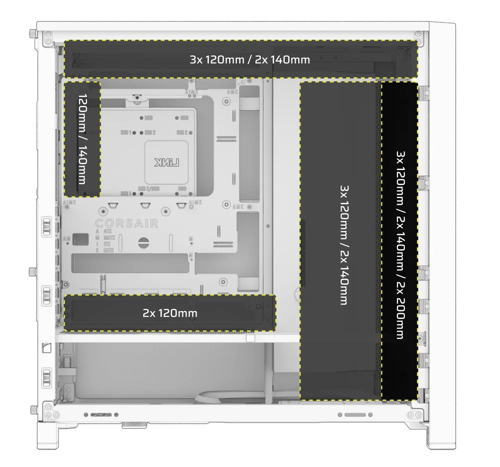
1. FAN LOCATIONS
|
Front |
Top |
Rear |
Side |
PSU Shroud | |
|
3x 120mm 2x 140mm 2x 200mm |
3x 120mm 2x 140mm
|
1x 120mm 1x 140mm
|
3x 120mm 2x 140mm
|
2x 120mm |
|
2. INCLUDED FANS & CONTROLLERS
|
FRAME 4000D |
FRAME 4000D RS | FRAME 4000D RS ARGB | Included Controlers |
|
None |
3x RS120 Pre-Installed | 3x RS120 ARGB Pre-Installed | None |
3. RADIATOR COMPATIBILITY
|
Front |
Top |
Rear |
Side |
PSU Shroud |
|
240mm 280mm 360mm |
240mm 280mm 360mm |
120mm 140mm |
240mm 280mm 360mm |
None |
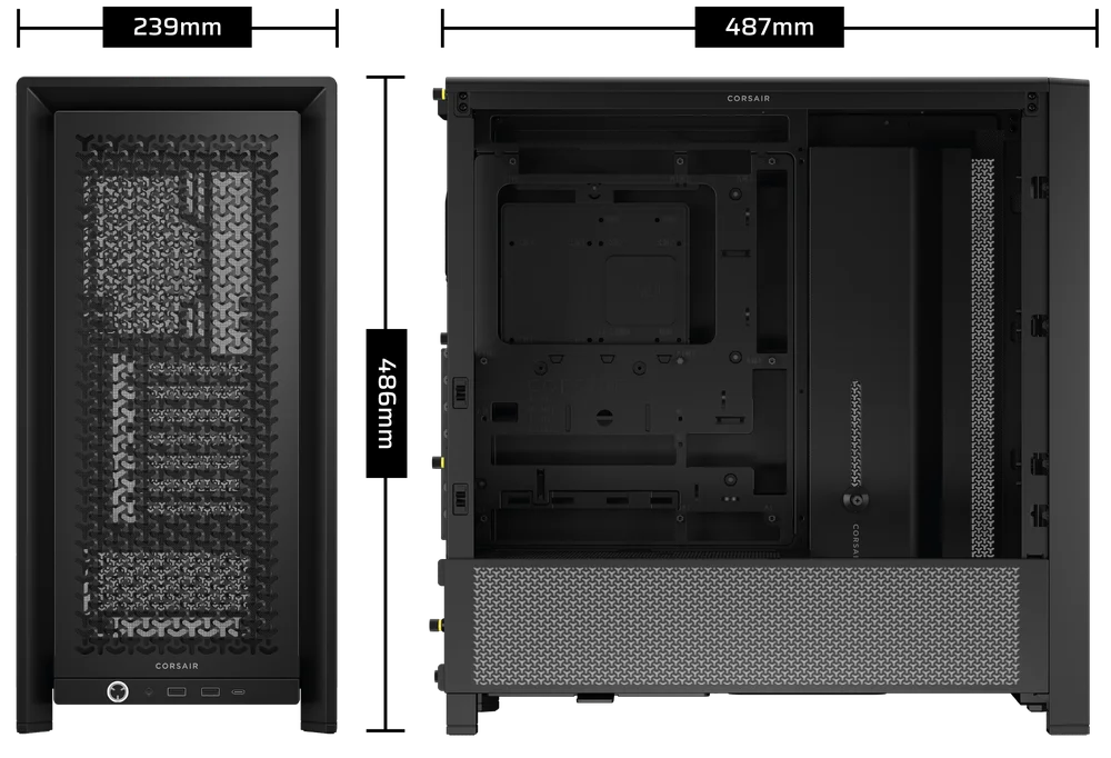
4. CASE DIMENSIONS
| Dimensions |
487mm x 239mm x 486mm |
|
Max GPU Length |
430mm |
|
Max CPU Cooler Height |
170mm |
|
Max PSU Length |
220mm |
ACCESSORY KIT CONTENTS
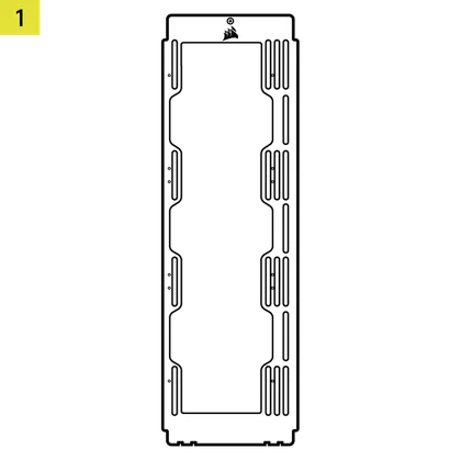
1x Side Fan Mounting Bracket
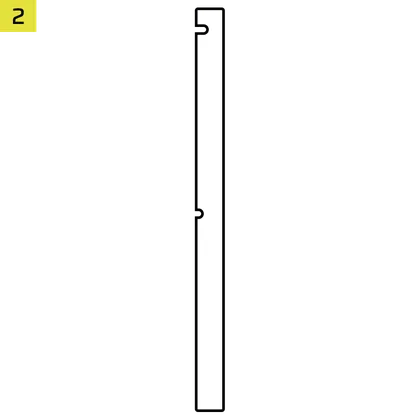
1x Reverse Connector Magnetic Strip
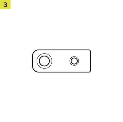
12x InfiniRail Fan Mounts
(Pre-Installed on Some Cases)
1x Solid Side Insert

1x Anti-sag Stabilization Arm Mini Mount
1x Anti-sag Stabilization Arm Rubber Spacer
28x Self-Tapping Fans Screws
8x Long Fan Screws (6-32 UNC)
18x Motherboard/HDD Screws (6-32 UNC; 6mm)

16x SSD Screws (M3 x 0.5; 5mm)
1x Spare Motherboard Standoff

2x Vertical Mount Standoffs
InfiniRail Fan Mount Lock Screws
(Pre-Installed on RS/RS ARGB)
1x Front I/O Adapter Cable
3x RS120 / RS 120 ARGB Fans
(Pre-installed on FRAME 4000D RS / FRAME 4000D RS ARGB)
CASE EXPANDED VIEW

| A. Three-Quarter Side Glass Panel | H. Side Fan Filter |
| B. PCI Plate | I. Front Panel |
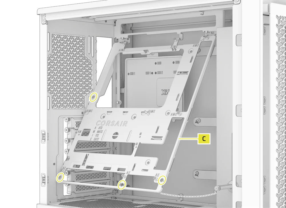
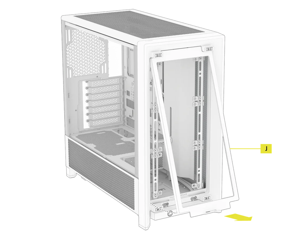
| C. Standard Steel Motherboard Tray | J. Front Fan Filter |
| D. Top Panel | K. PSU Fan Filter |
| E. Drive / Controller Plate | L. PSU Shroud |
| F. Cable Shroud | M. Translucent Side Insert |
| G. Steel Side Panel | N. Quarter-Mesh Side Panel |
PANEL INSTALLATION / REMOVAL
WARNING: This product contains tempered glass. Handle with care.
- To prevent damage or injury, avoid placing or storing the case on hard surfaces such as ceramic or porcelain tile, stone, masonry, or concrete.
- CORSAIR strongly recommends removing all tempered glass side panels before positioning the case or beginning your build on a hard surface.
- If you must place the finished build on a hard surface, elevate or isolate the case to minimize the risk of accidental contact, damage, or personal injury.
- Tempered glass panels include an anti-shatter film for safety reasons. Do not remove this safety film from the glass or it will damage the panel.
Replacement panels are available at www.corsair.com. Contact help.corsair.com for any assistance.
1. SIDE PANELS REMOVAL
The FRAME 4000 has a split side glass/mesh that can be removed independently depending on what you need to do.
- To remove the top Three-Quarter Side Glass Panel (A), unscrew the panel at the back of the case and swing the glass off the tabs in the front of the case.
- To remove the lower Quarter Mesh Side Panel (N), unscrew the panel at the back of the case and swing the mesh off the tabs in the front of the case.
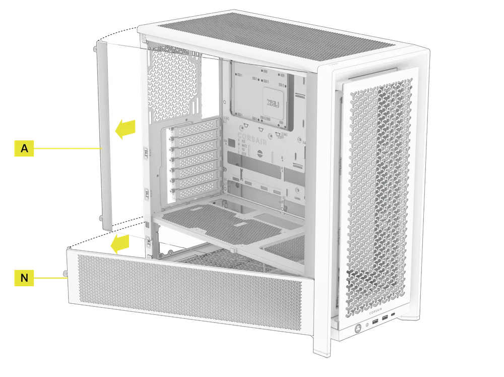
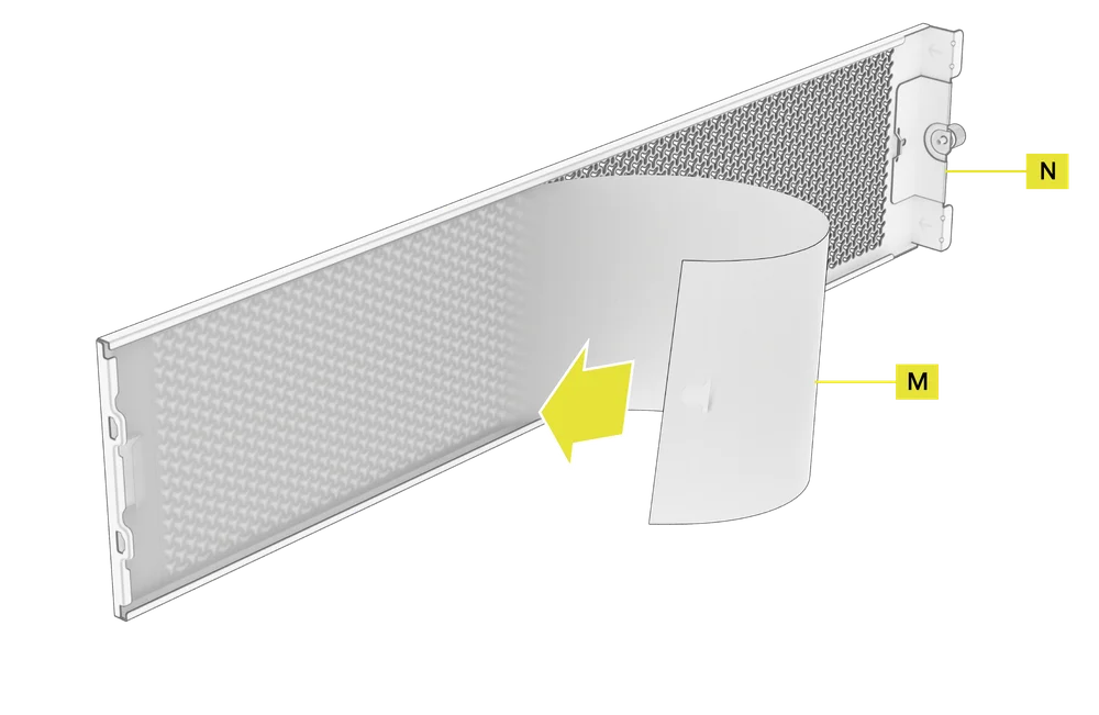
NOTE: The Quarter Mesh Side Panel (N) comes with two optional inserts to customize the look and function of your build. A Translucent Side Insert (M) is pre-installed, allowing RGB lighting to shine through while partially concealing cables. Alternatively, you can swap in a Solid Side Insert (4) for full coverage, or leave the panel open for maximum airflow. Each insert slides under the long edges of the panel, making installation and removal quick and easy.
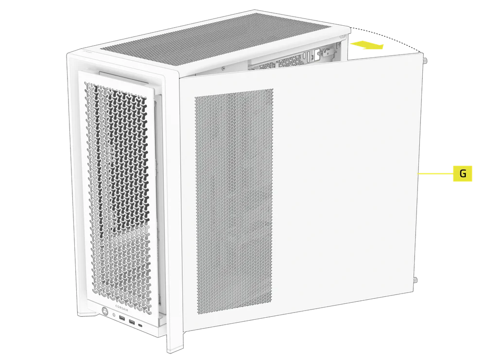
- To remove the Steel Side Panel (G), unscrew the panel at the back of the case and swing the panel off from the tabs towards the front of the case.
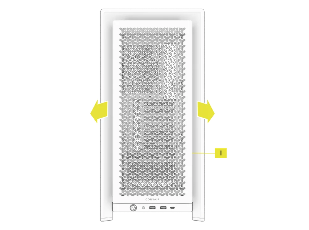
2. FRONT PANEL REMOVAL
- Pull the Front Panel (I) outward. It's secured by two ball snaps at the top and bottom.
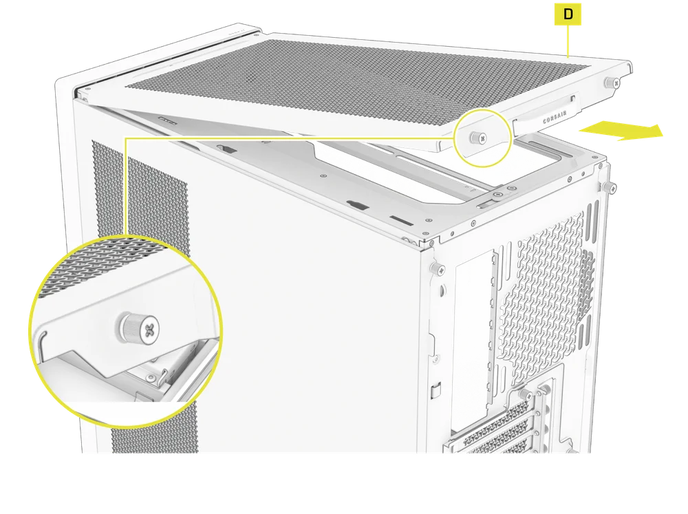
3. TOP PANEL REMOVAL
- Unscrew the two captive thumbscrews in the rear and pull the rubberized strap to remove the Top Panel (D).
WARNING: The rubber pull-grip on the Top Panel (D) is design to assist in removing the top panel from the case.
This is not a handle to lift the case or your system. If you lift your case by this pull-grip, you risk serious damage to your PC, case and self.
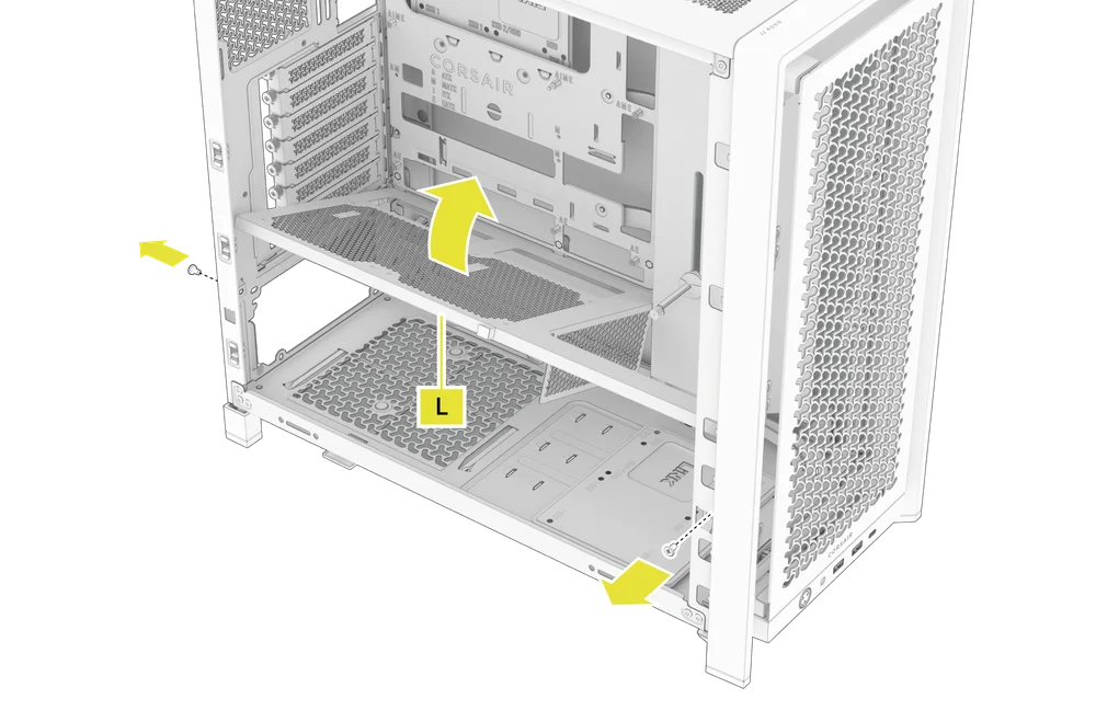
4. PSU SHROUD REMOVAL
The PSU Shroud (L) is held in with a screw in the front of the case along the side and a screw in the rear panel of the case.
- Remove these two screws and the shroud will lift out.
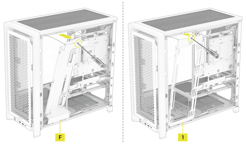
5. CABLE SHROUD OR SIDE FAN MOUNT REMOVAL
- Unscrew the screw at the top of the mount and tip the mount or cable cover out of the side. Repeat this in reverse to reinstall the part of your choice.
6. MOTHERBOARD TRAY REMOVAL
The Standard Steel Motherboard Tray (C) is held in by 4 screws along the back of the tray.
- Unscrew these four screws, tilt the tray outward and lift it out.
7. FRONT PANEL I/O REMOVAL
The Front Panel I/O is held in with two screws on the bottom of the case.
- To remove it, simply unscrew these two screws, and the entire Front Panel I/O assembly can be lifted out.
- To reinstall the Front Panel I/O or to install a new one, place the assembly back in position and secure it with the same two screws.
MOTHERBOARD INSTALLATION
INSTALLING A MOTHERBOARD
The FRAME 4000 supports mITX, mATX, ATX, and E-ATX motherboards, including ASUS BTF, MSI Project Zero, and Gigabyte Project Stealth with reversed power connections.
- Align the motherboard with the standoffs and secure it with the provided Motherboard Screws (9).
NOTE: Before installation, ensure your motherboard I/O shield is in place, if required.
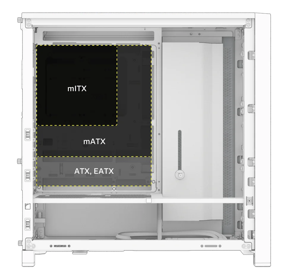
TIP: If the pre-installed standoffs don't align with the holes on your motherboard, remove any unused ones and reposition them to match the open mounting points on your motherboard.
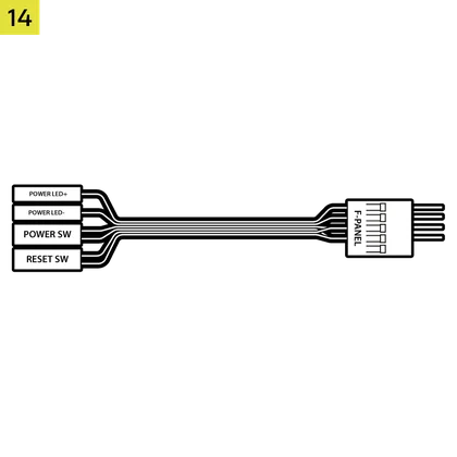
FRONT I/O CABLES INSTALLATION
1. STANDARD INTEL MOTHERBOARDS
- Connect the FPANEL plug to the front panel I/O header on your motherboard, aligning it with the keyed layout. This header is often labeled JFP1 on some motherboards.
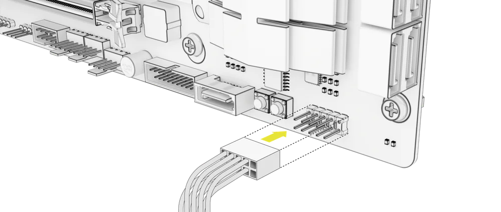
TIP: If your PC doesn't power on or shows issues when using the FPANEL plug, try using the included Front I/O Adapter Cable (14) to ensure proper connection to the motherboard header.
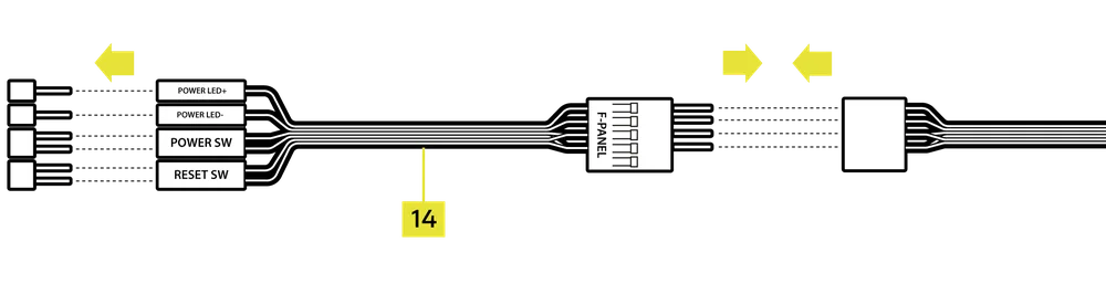
NOTE: This case does not include an HDD LED or Reset Switch, so while these connectors appear on the Front I/O Adapter Cable (14), they are not functional and have been intentionally left unpopulated.
2. AMD OR NON-STANDARD INTEL MOTHERBOARDS
- Use the included Top-mounted Front I/O Adapter (14) to connect the FPANEL plug to the individual front panel I/O header pins.
3. FRONT I/O EXPLANATION
- FRAME 4000D
- FRAME 4000D RS
- FRAME 4000D RS ARGB
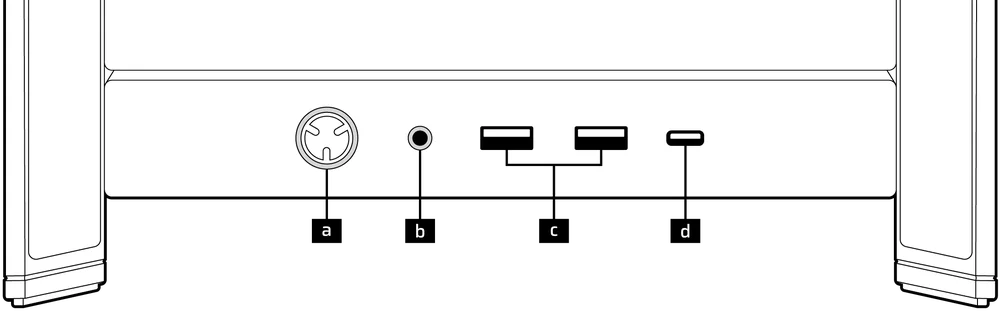
| a. Power Button + LED | c. 2x USB 3.2 Gen 1 Type-A (5 Gbps) |
| b. Headphone / Mic Combination Jack | d. 1x USB 3.2 Gen 2x2 Type-C (20 Gbps) |
- FRAME 4000D LCD RS ARGB
- FRAME 4000D VAULT SERIES
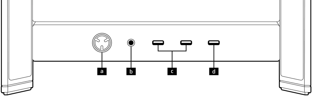
| a. Power Button + LED | c. 2x USB 3.2 Gen 1 Type-C (5 Gbps) |
| b. Headphone / Mic Combination Jack | d. 1x USB 3.2 Gen 2x2 Type-C (20 Gbps) |
4. FRONT I/O CONNECTIONS
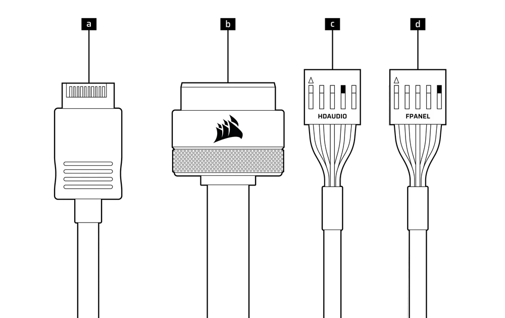
| a. USB 3.2 Type-E (20 Gbps) | c. HD Audio (Headphone, Microphone) |
| b. USB 3.0 | d. FPANEL (Power LED, Power Button) |
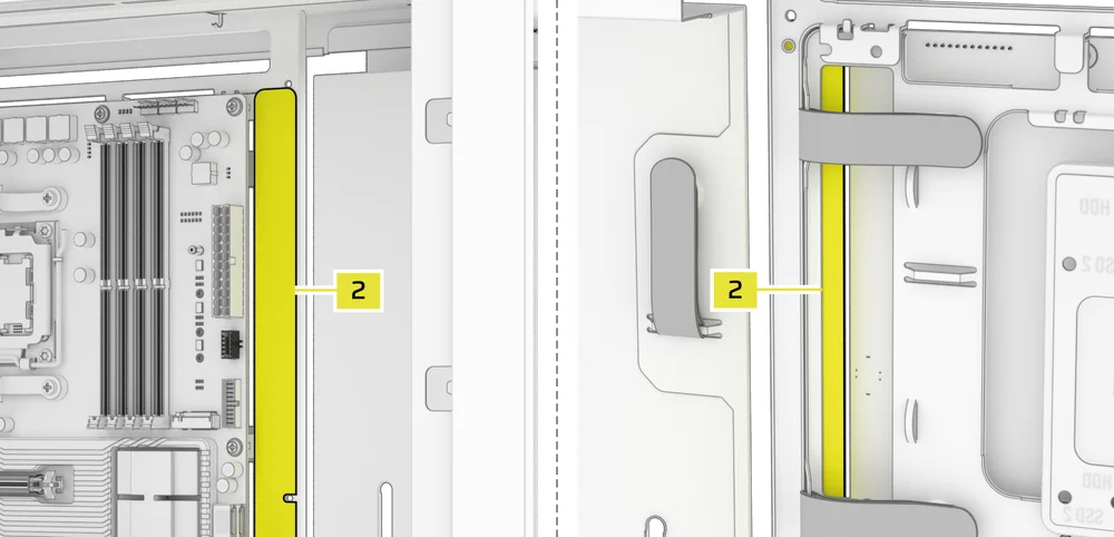
MAGNETIC STRIP INSTALLATION
The FRAME 4000 includes a Reverse Connector Magnetic Strip (2) that is designed to cover the visible edge of the reverse connector holes in the motherboard tray.
- Align the Reverse Connector Magnetic Strip (2) to your standoffs and adjust side to side to close the gap on your motherboard.

1. MOTHERBOARD WITH REVERSE CONNECTORS
If you're installing a motherboard with reverse connectors, the Reverse Connector Magnetic Strip (2) can be used to fill the gap around the 24-pin ATX port, providing a cleaner and more polished appearance.
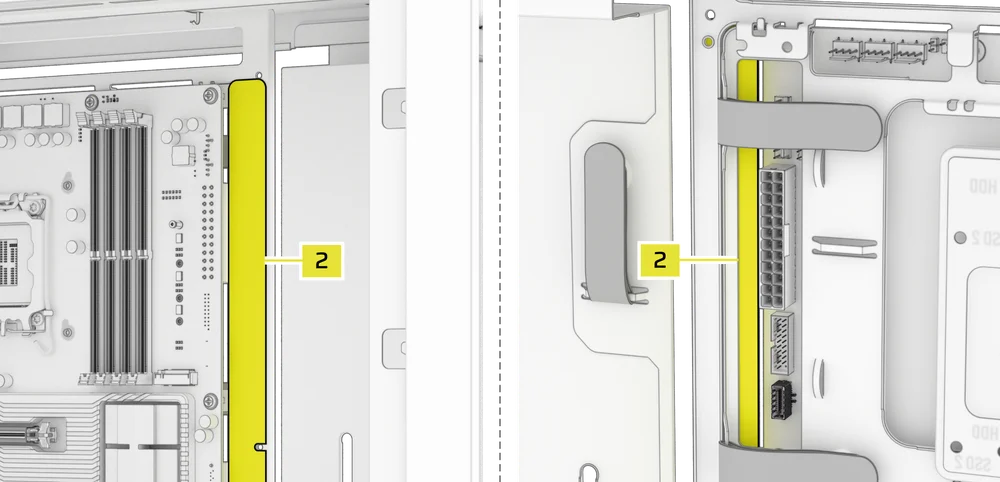
2. MOTHERBOARDS WITH STANDARD CONNECTORS
When installing a standard motherboard, you can slide the Reverse Connector Magnetic Strip (2) behind the board, aligning it with the screw holes along the motherboard tray, to cover the reverse connector slot and conceal any wires running along the motherboard tray for a cleaner look.
TIP: The magnetic strip features cut-out slots, allowing you to install it simultaneously with an yanti-sag stabilization arm mini mount.
FAN INSTALLATION
The FRAME 4000 can mount up to 12x 120mm or 7x 140mm on the top, side, and rear of the case.
|
Front |
Top |
Rear |
Side |
PSU Shroud | |
|
3x 120mm 2x 140mm 2x 200mm |
3x 120mm 2x 140mm
|
1x 120mm 1x 140mm
|
3x 120mm 2x 140mm
|
2x 120mm |
|
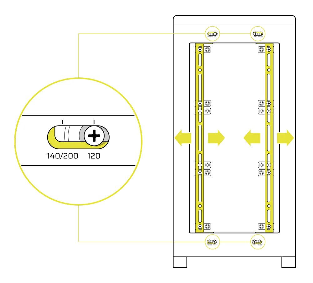
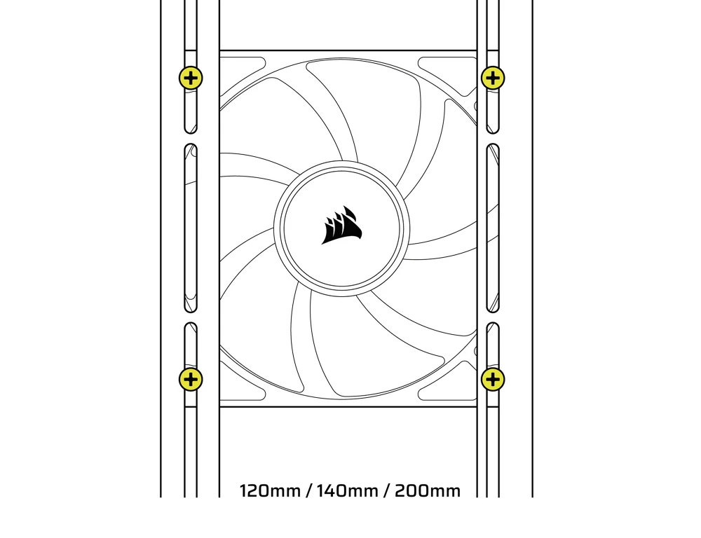
1. USING THE INFINIRAIL FAN MOUNTING SYSTEM
CORSAIR's InfiniRail is an innovative fan and radiator mounting system designed to offer exceptional flexibility and ease of use in PC case builds. Unlike traditional cases with fixed mounting points, InfiniRail utilizes adjustable steel rails that allow users to slide and position fans and radiators precisely where needed.
The FRAME 4000 features two of these InfiniRail systems; one on the top and one on the front.
NOTE: Determine the size and placement of your fans before configuring the rails. You do not have to fully remove the InfiniRail Philips head screws.
Adjusting the Rails in the Front of the Case
- Loosen the Philips head screw on both ends of the InfiniRails.
- Adjust both front rails for your fans according to the markings on the case.
WARNING: In order to install 200mm fans in the front, you may need to remove the PSU shroud.
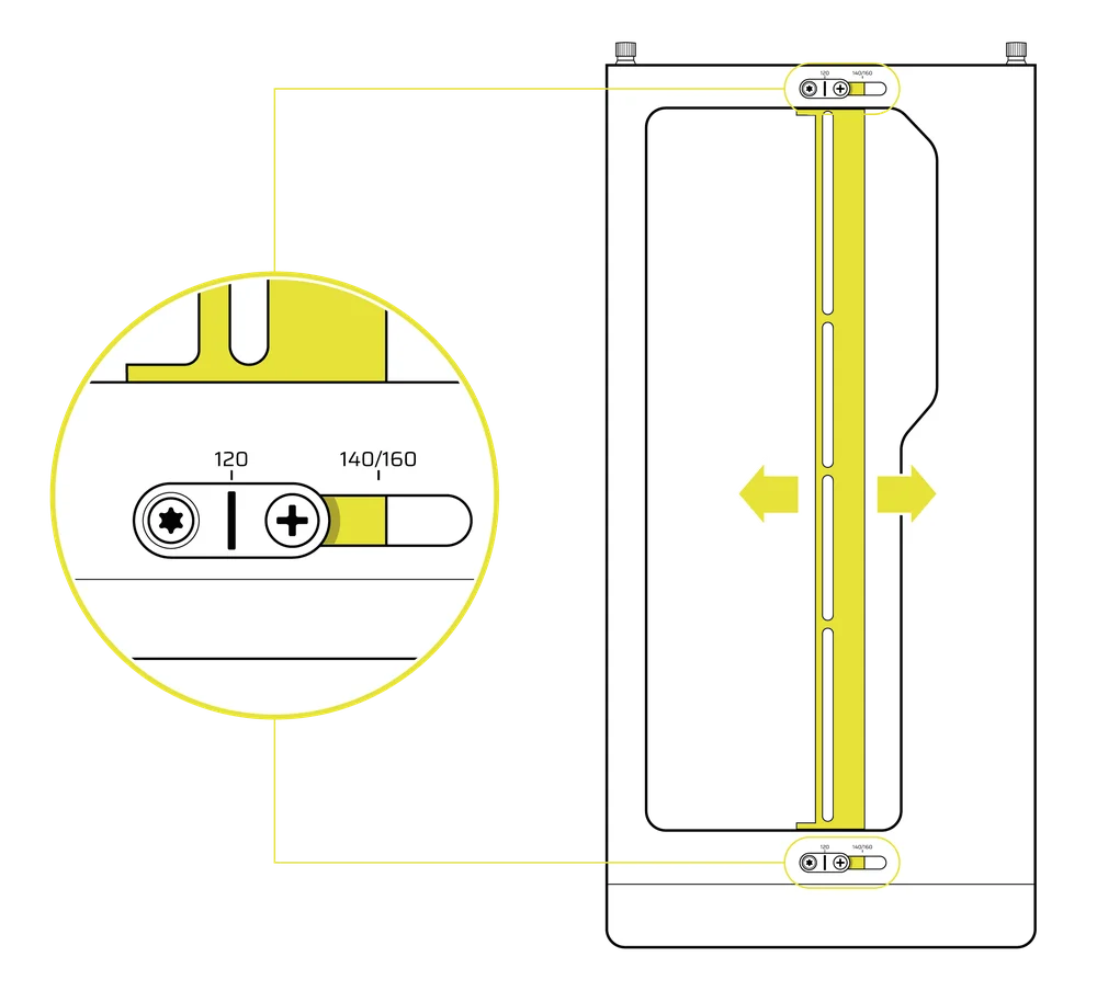
Adjusting the Rail on the Top of the Case
- Loosen the Philips head screw on both ends of the InfiniRail.
- Adjust the the top rail for your fans according to the markings on the case.
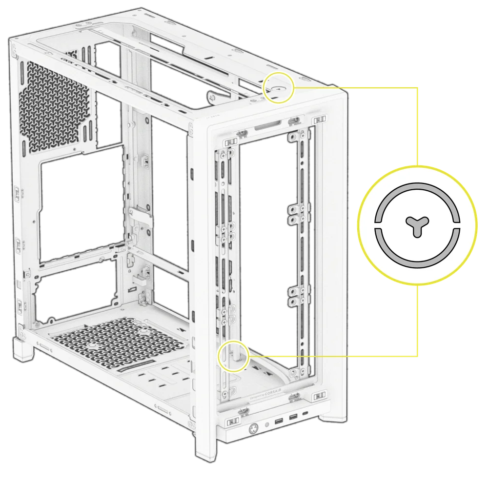
IMPORTANT: Screws using non-standard head patterns are not meant to be removed.
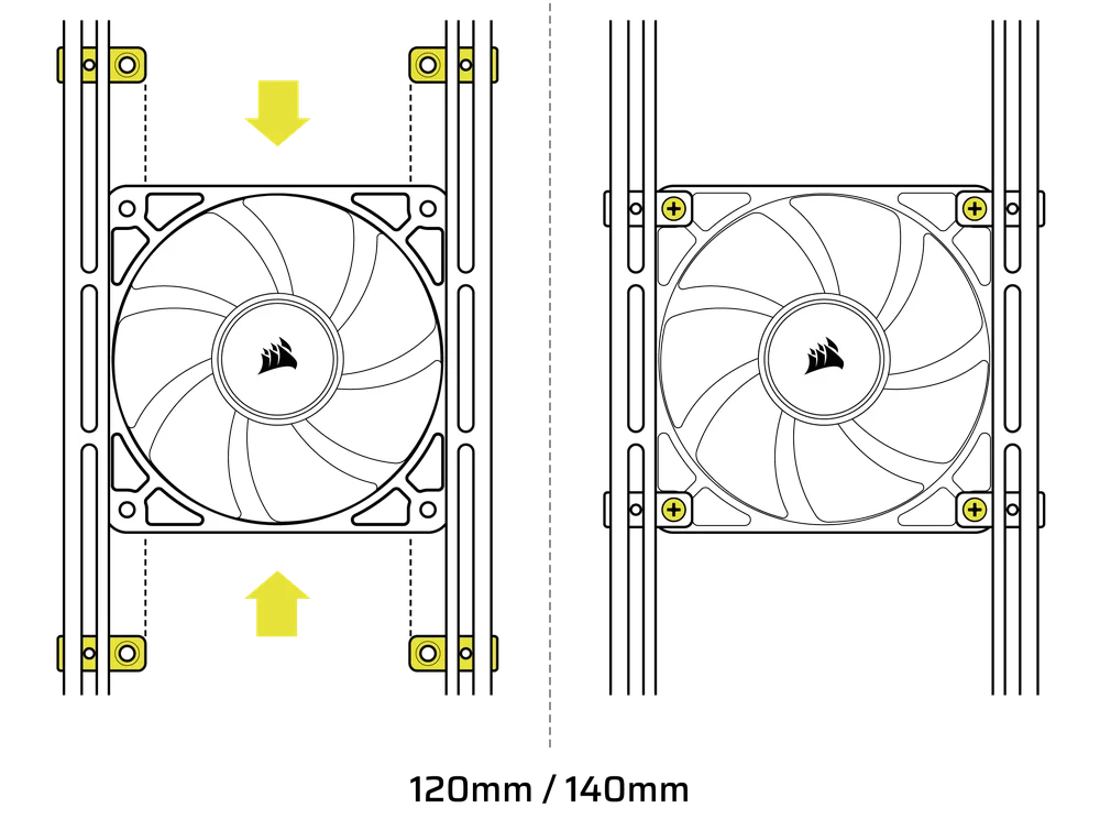
2. INSTALLING FANS IN THE FRONT
Installing 120mm or 140mm Fans
To install 120mm or 140mm fans using the front InfiniRail Fan Mounting System, you need to install the InfiniRail Fan Mounts (3). Use four mounts per fan, two on each side of the rails.
NOTE: Some cases might come with InfiniRail Fan Mounts pre-installed.
- Clip the InfiniRail Fan Mounts (3) onto the rails by anchoring the inner edge of each mount first, then snapping the outer edge into place.
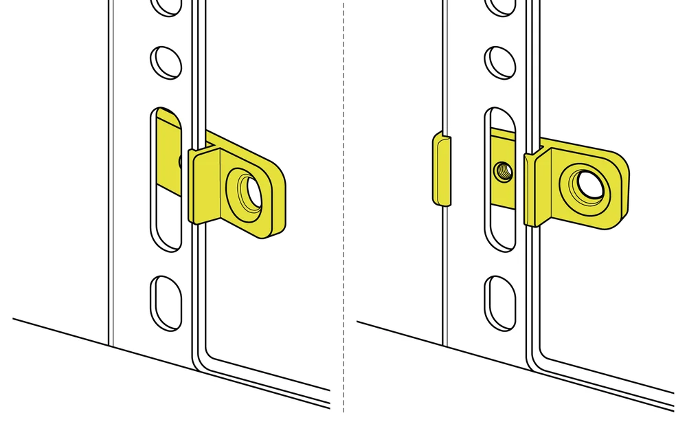
- Slide the mounts along the rails to align them with your fan mounting points.
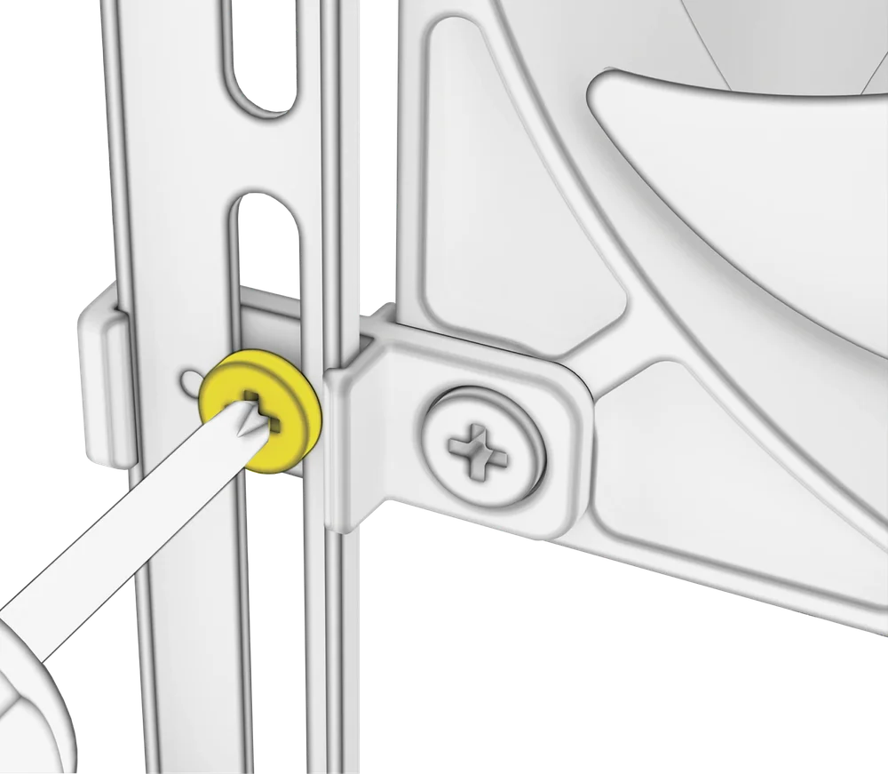
- Align your fans to the mounting tabs on the mounts and secure them by screwing in Self-Tapping Fans Screws (7).
- Once aligned, you can lock the setup in place with the InfiniRail Fan Mount Lock Screws (13).
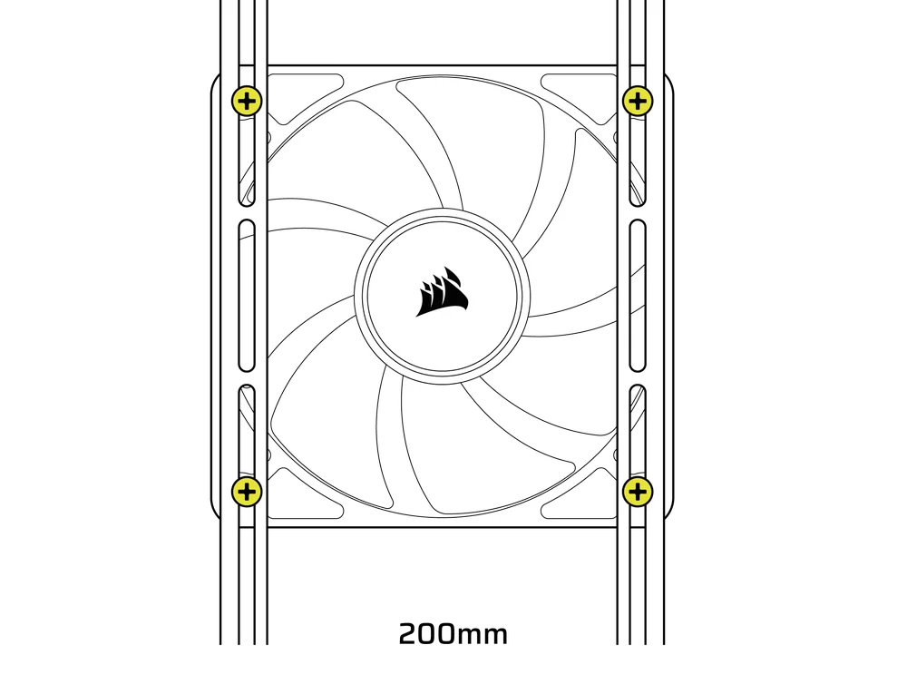
Installing 200mm Fans
200mm fans will screw directly into the InfiniRail mounts without the plastic fan mounts. Remove the mounts if they came pre-installed on your case.
- Align your fans to the mounting slots on the InfiniRails and secure them by screwing Self-Tapping Fans Screws (7) into the fan frame.
NOTE: Select 200mm fans may require you to remove the PSU shroud to fit.
3. INSTALLING FANS ON THE TOP
- Align your fans to the InfiniRail fan mounting slots and and secure them by screwing Self-Tapping Fans Screws (7) into the fan frame.
4. INSTALLING FANS ON THE SIDE
To install fans on the side, ensure you have the Side Fan Mounting Bracket (1) installed.
- Align your fans to the fan mounting slots, and and secure them by screwing Self-Tapping Fans Screws (7) into the fan frame.
TIP: Use the dots marked on the Side Fan Mounting Bracket (1) to serve as centering guides.
5. INSTALLING FANS ON THE PSU SHROUD
- Align your fans to the fan mounting holes on the PSU Shroud (L)
- Secure the fans with Long Fan Screws (8).
6. INSTALLING FANS IN THE REAR
- Align your fan to the fan mounting holes.
- Secure the fan by screwing in Self-Tapping Fans Screws (7).
HYDRO X CUSTOM COOLING SUPPORT
FRAME 4000 has fill / drain ports pre-punched in the top and bottom panels for a Hydro X open loop liquid cooling setup.
- Remove the port covers by gently prying them off with a flathead screwdriver.
RADIATOR INSTALLATION
The FRAME 4000 offers several locations to mount a radiator for liquid cooling, with the front and top locations featuring an adjustable InfiniRail fan mount. Please refer to the Fan Installation section for details on using the InfiniRail Fan Mounting System.
TIP: For optimal noise, thermal performance, and reliability, ensure the radiator is mounted higher than the pump when using an AIO.
|
Front |
Top |
Rear |
Side |
PSU Shroud |
|
240mm 280mm 360mm |
240mm 280mm 360mm |
120mm 140mm |
240mm 280mm 360mm |
None |

Top mounting provides optimal noise performance, but other mounts can be utilized based on your build preferences. Consult your cooler's product manual for more tips on usage and best practices.
NOTE: To center the radiator, you may need to remove one radiator mounting screw. Using eleven screws still provides sufficient mounting points to securely install the radiator and fans.

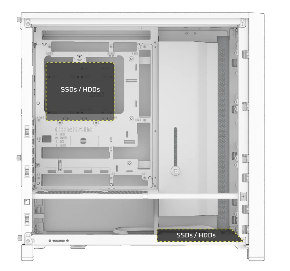
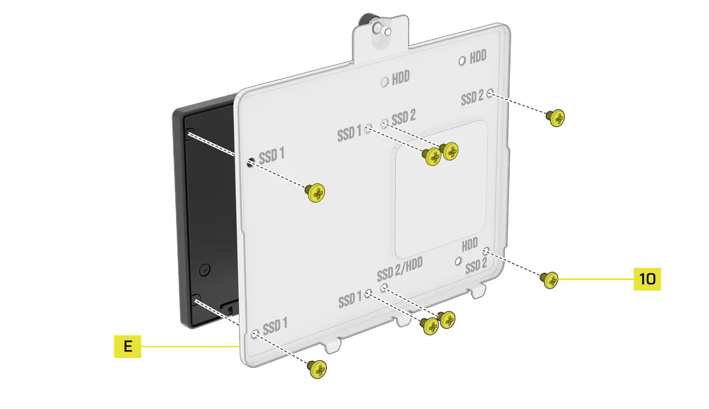
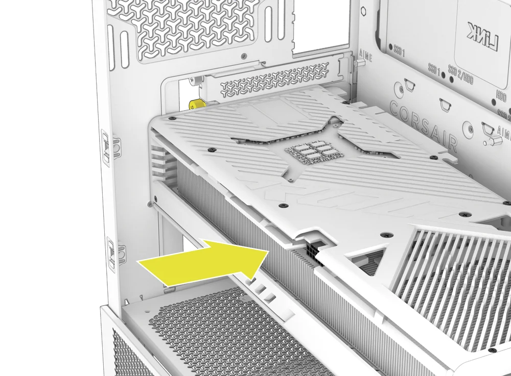
INSTALLATION OF STORAGE DEVICES AND CONTROLLERS
The FRAME 4000 includes two Combination Drive Plates (E) - each capable of mounting one HDD or two SSDs. Using both plates you can choose between 2x HDDs, 4x SSDs, or a 1x HDD with 2x SSDs.
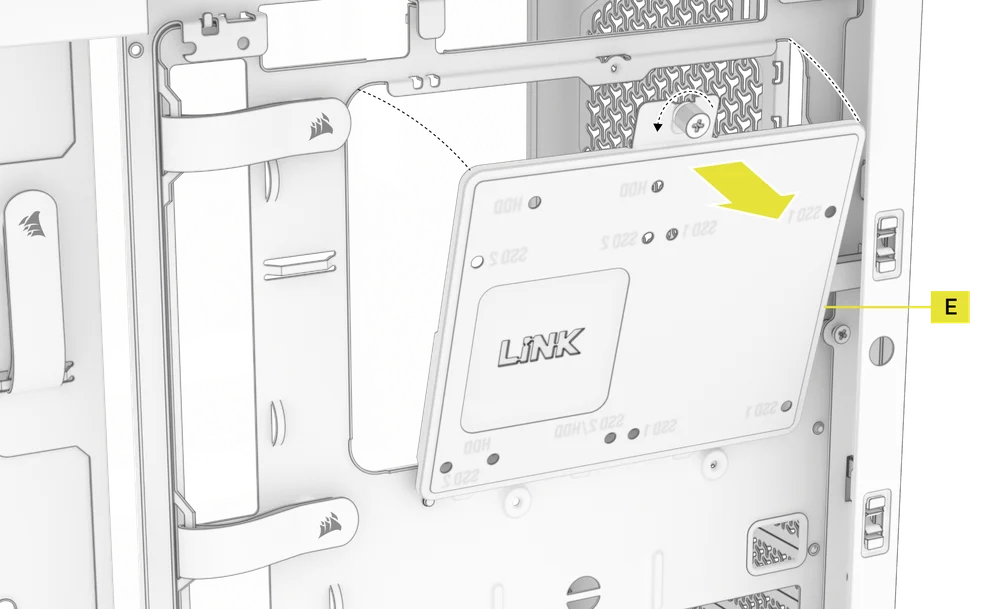
1. COMBINATION DRIVE PLATE REMOVAL
- Unscrew the thumbscrew securing the Combination Drive Plate (E), then remove the plate.
2. SSD INSTALLATION ON THE COMBINATION DRIVE PLATE
- Install the SSD(s) onto the Combination Drive Plate (E) by securing it to the bottom of the plate using the included SSD Screws (10).
3. HDD INSTALLATION ON THE COMBINATION DRIVE PLATE
- Install the HDD onto the Combination Drive Plate (E) by securing it to the bottom of the plate using the included HDD Screws (9).
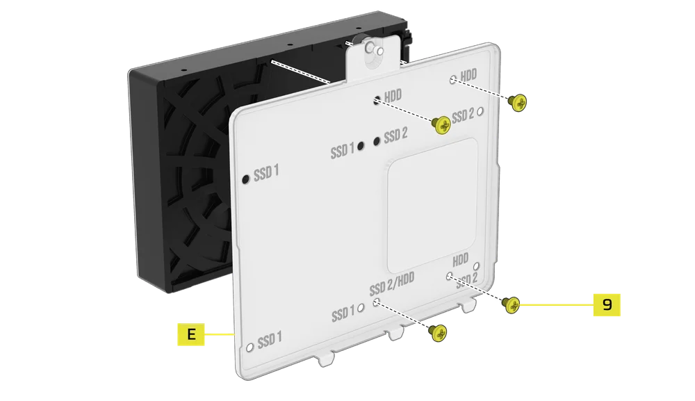
The Combination Drive Plate (E) also serves as a mounting location for an iCUE LINK System Hub controller, if one is used.
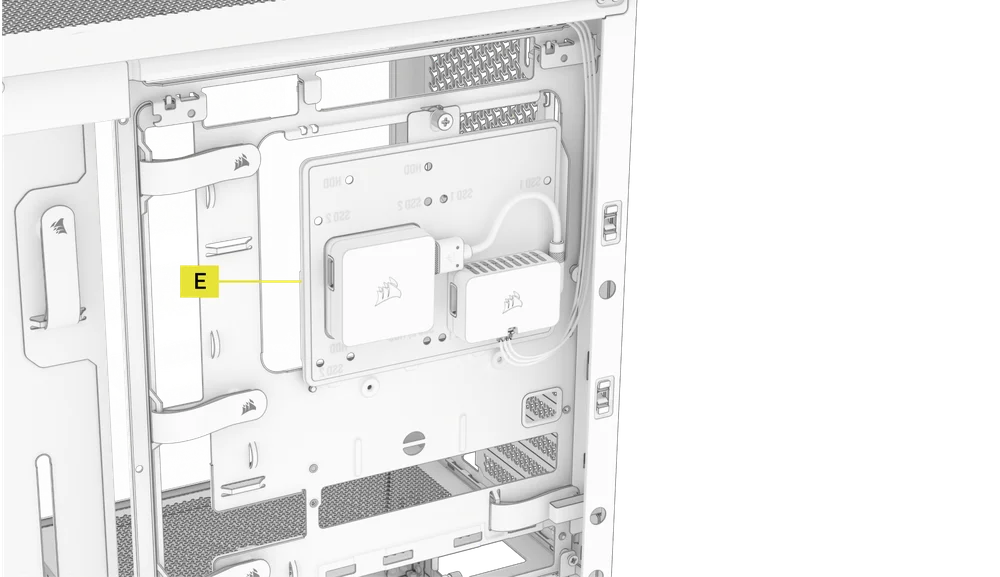
4. SECURING THE COMBINATION DRIVE PLATE
Reinsert the Combination Drive Plate (E) into its designated slot in the case, then secure it by tightening the thumbscrew clockwise.
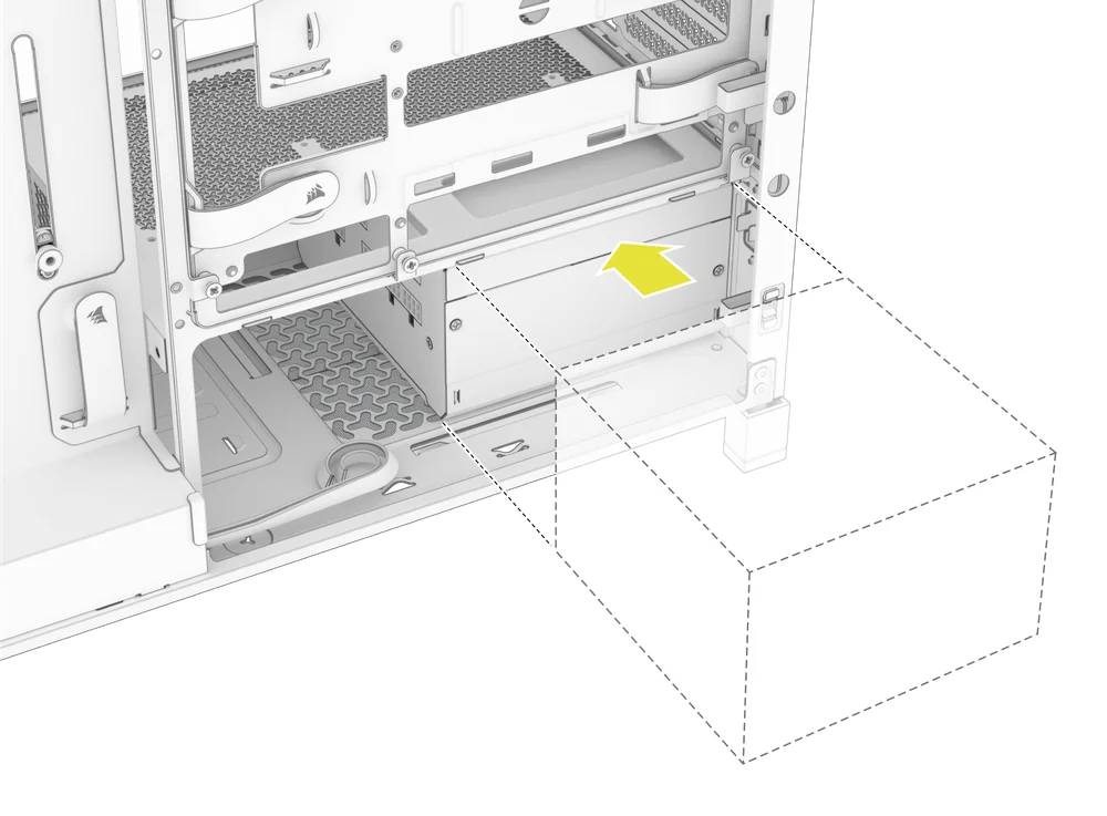
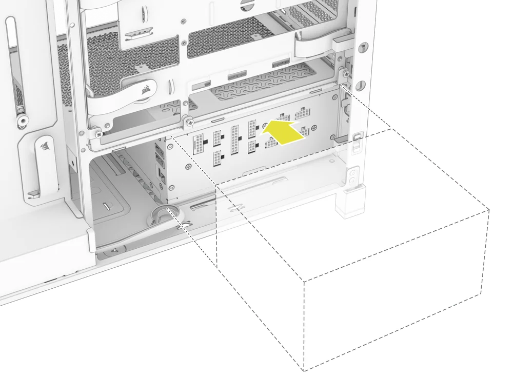
POWER SUPPLY INSTALLATION
1. STANDARD PSU INSTALLATION
- Install the PSU with the fan facing down.
- Secure the power supply to the chassis with the two captive screws located on the back of the case.
- For additional security, secure the PSU using two Motherboard Screws (9) screws in the corners of the rear panel.
2. CORSAIR SHIFT POWER SUPPLY INSTALLATION
The FRAME 4000 is fully compatible with all SHIFT power supplies and installs identically to a standard ATX PSU.
GRAPHICS CARD INSTALLATION
The included PCI bracket allows the FRAME 4000 to support both horizontal and vertical GPU mounting configurations.
TIP: For easier assembly, install the GPU as the final step.
1. INSTALLING A GPU IN A STANDARD ORIENTATION
- Unscrew the PCIe slot covers and remove them.
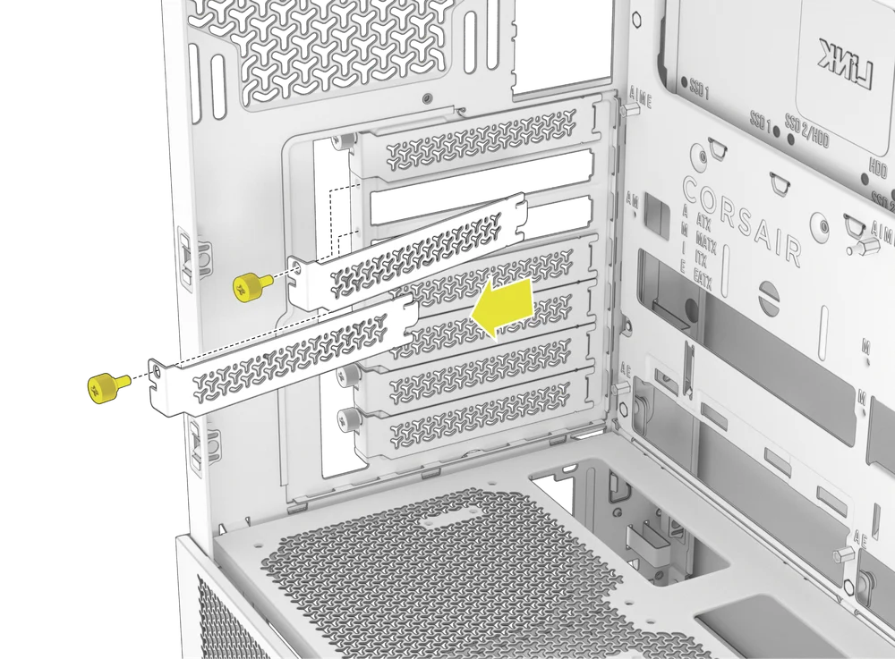
- Insert the card into the PCIe slot until it clicks into place with the PCIe slot's retention retention mechanism.
- Align the bracket with the PCIe slots and secure the card to the case.
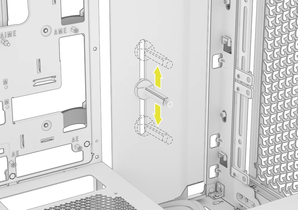
2. USING THE GPU ANTI-SAG STABILIZATION ARM
The GPU Anti-sag Stabilization Arm supports your graphics card, preventing it from bending or sagging under the weight of its heatsink. This not only helps protect your graphics card and PCIe slot, but also contributes to a cleaner, more professional-looking build.
- Adjust the GPU Anti-Sag Arm by loosening the front-facing thumbscrew and sliding it up or down.
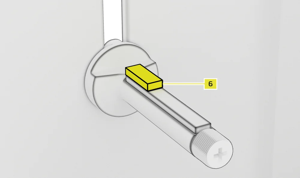
NOTE: If your GPU fan or other parts come into contact with the rubber arm, use the included Anti-sag Stabilization Arm Rubber Spacer (6) from the accessory box to ensure clearance from any moving parts.
- Attach the self-adhesive Anti-sag Stabilization Arm Rubber Spacer (6) to the GPU Anti-Sag Arm.
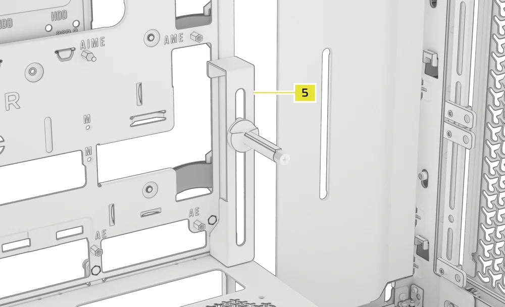
TIP: If you decide to swap the Cable Shroud (F) for the Side Fan Mounting Bracket (1), you can relocate your GPU Anti-sag Stabilization Arm to the Anti-sag Stabilization Arm Mini Mount (5) and retain anti-sag functionality.
3. INSTALLING A GPU IN A VERTICAL ORIENTATION
The FRAME 4000 supports vertical GPU mounting with the included PCI Plate (B) and a PCIe Riser Card (sold separately).
- Uninstall the PCI Plate (B) by removing the three screws at the rear of the case.
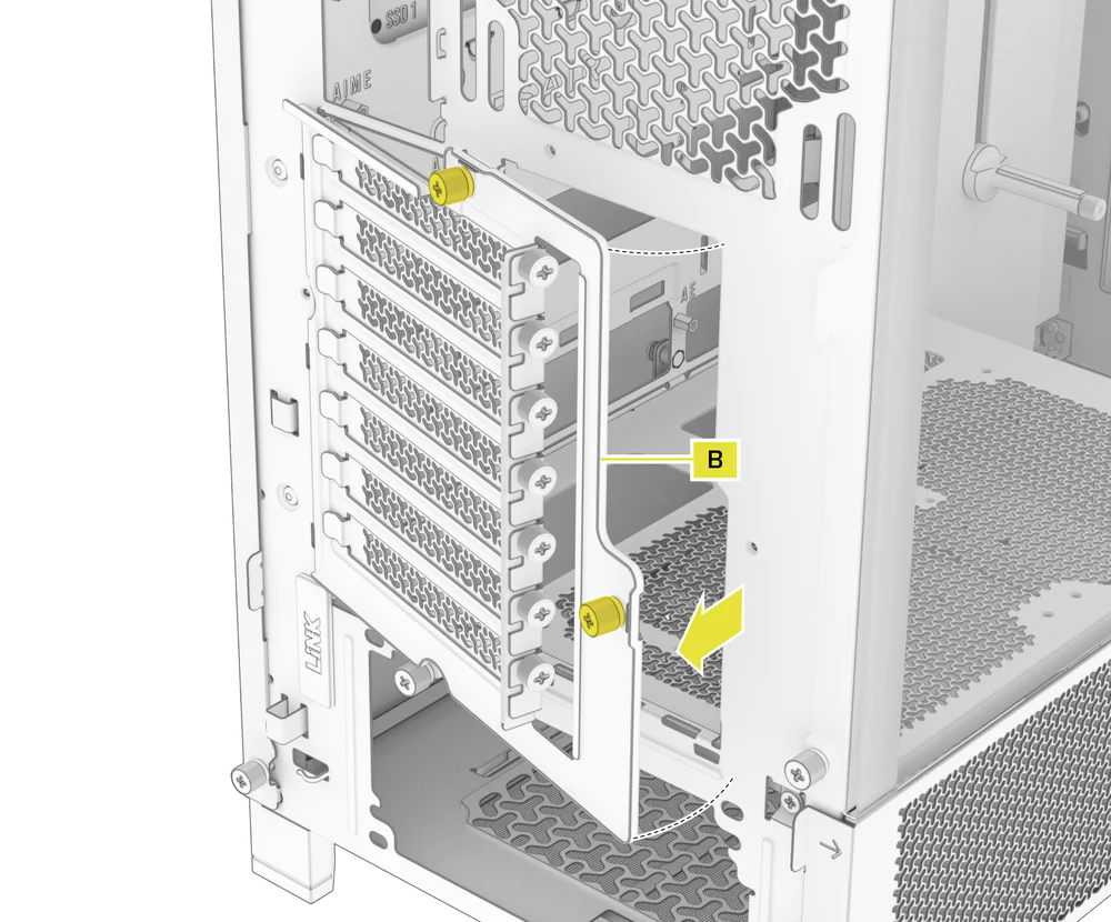
NOTE: The PCI Plate thumbscrews are captive and do not need to be fully removed.
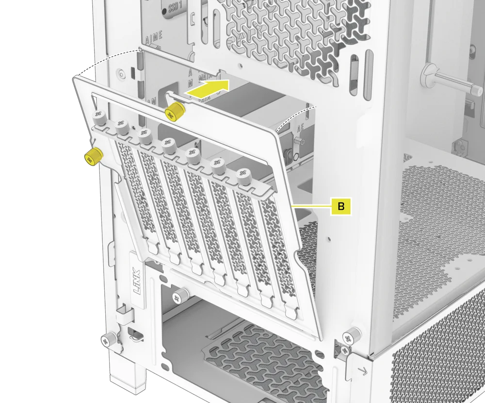
- Rotate the PCI Plate (B) 90 degrees counterclockwise so that the PCIe slot cover thumbscrews face upward.
- Re-attach the PCI Plate (B) and secure the thumbscrews.
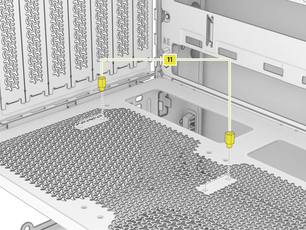
- Install the Vertical Mount Standoffs (11) from the accessory box to the top of the PSU shroud. There are two locations for standoffs, so choose the location that best suits the size of your GPU in relation to how far it is from the side panel.
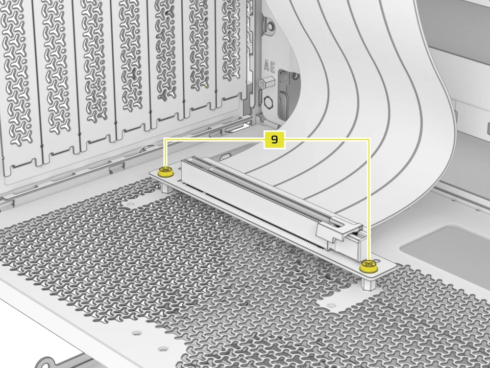
- Mount the PCIe Riser Card (sold separately) to the Vertical Mount Standoffs (11) using two of the included Motherboard Screws (9).
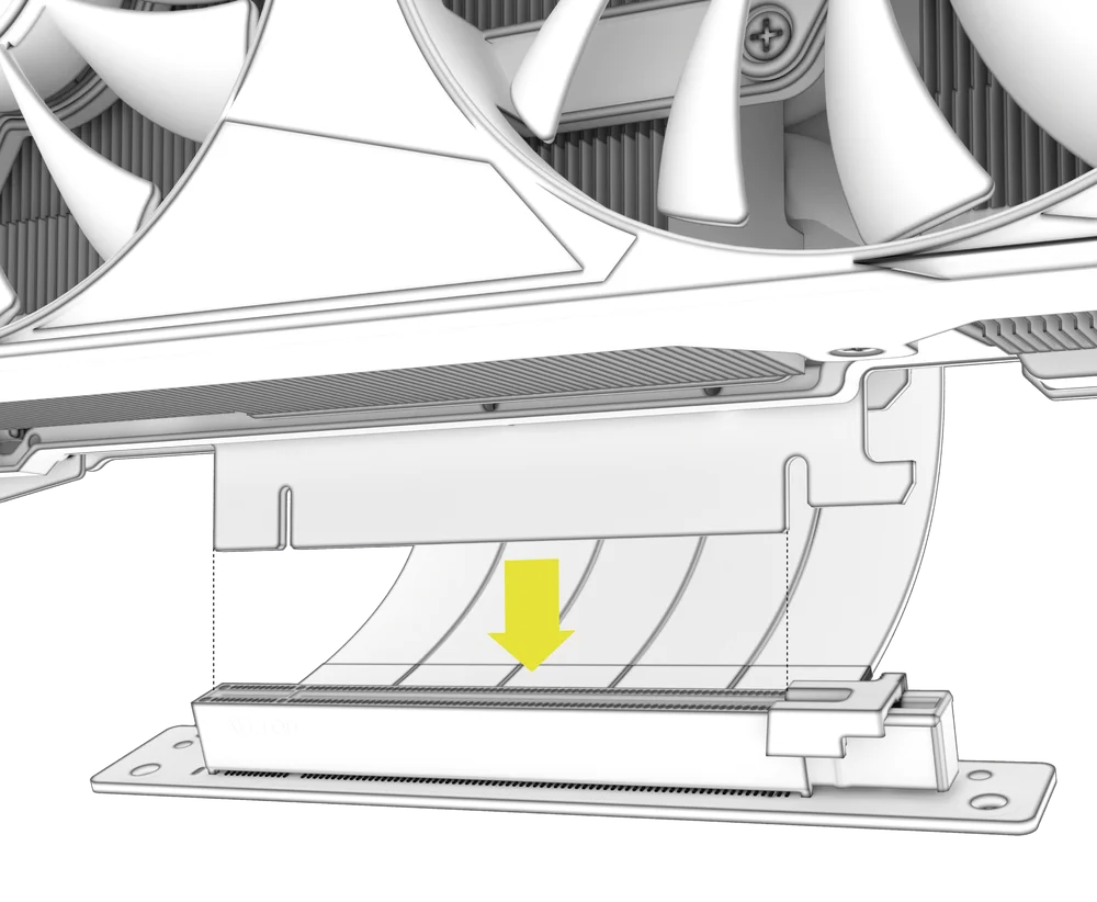
- Mount the GPU into the PCI bracket by firmly seating it into the riser card until it clicks, then secure it with thumbscrews.
CONNECTING YOUR FANS
1. CONNECTING AND CONTROLLING FANS FOR FRAME 4000D RS
Please visit the CORSAIR RS Series Quick Start Guide for instructions on fan installation.
2. CONNECTING AND CONTROLLING FANS FOR FRAME 4000D RS ARGB
Please visit the CORSAIR RS ARGB Series Quick Start Guide for instructions on fan installation.
MAINTENANCE
1. CLEANING YOUR CASE FILTERS
The FRAME 4000 features three removable dust filters. A power supply filter on the bottom, a magnetic filter on the side, and a plastic/nylon filter on the front.
- To remove the Front Fan Filter (J), tilt the plastic filter frame towards the top of the case, pulling from the bottom.
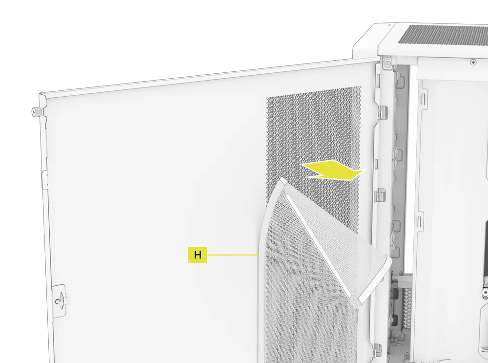
- To remove the magnetic Side Fan Filter (H), pull at the center to flex the frame, then detach the ends from the locking points and lift the filter away.
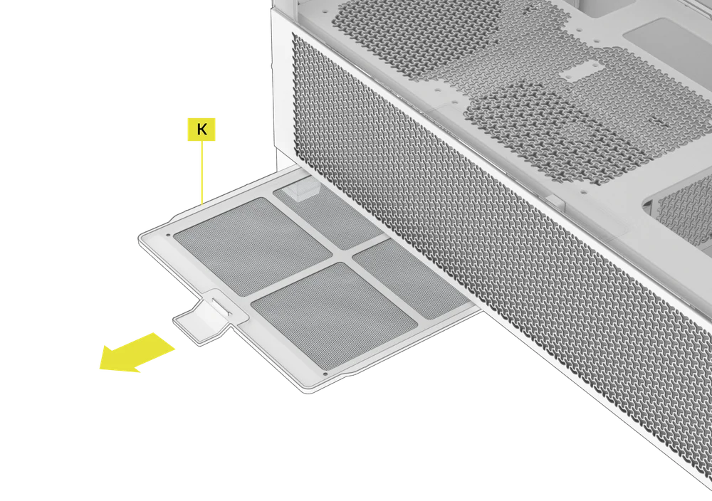
- To remove the PSU Fan Filter (K), pull it away from the case.
NOTE: Filters can be cleaned with pressurized air or water. If you rinse your filter, ensure filters are fully dry before reinstalling.
2. CABLE MANAGEMENT TIPS
The FRAME 4000 includes other various cable management features such as:
- Variable internal/external hook and loop straps for the rear of the case.
- Multiple positions for hook and loop straps to accommodate standard or reverse connector motherboards.
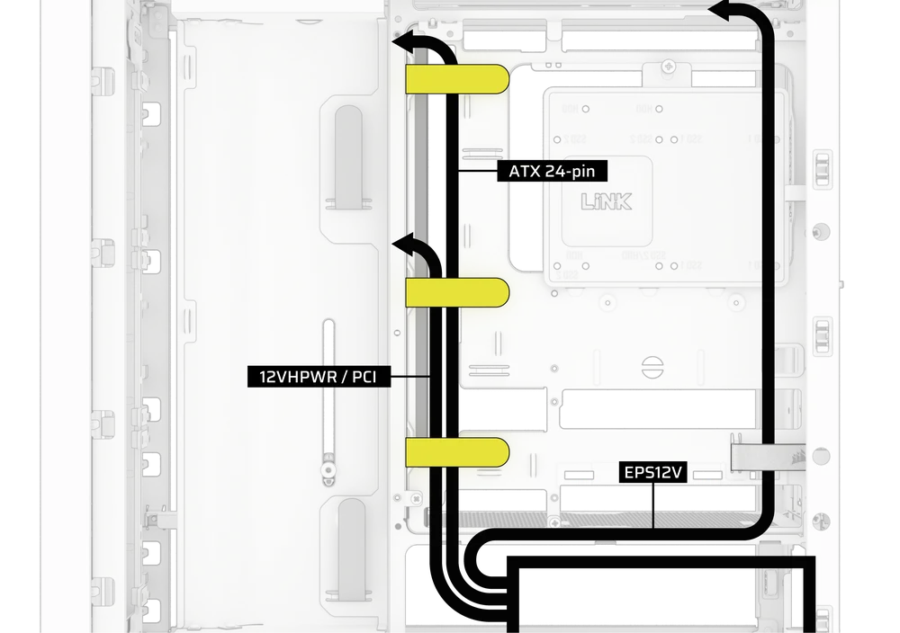
- Zip tie points are strategically placed for routing power cables to specific devices.
- iCUE LINK cable hooks in the top panel to securely hold LINK cables without permanent attachment.
- Supports most reverse connector motherboards (MSI, ASUS, Gigabyte) that feature connectors on the rear of the board for a build with no visible motherboard cables.
- A dedicated location for your iCUE LINK System Hub.
- If you don’t feel like spending much time on cable management and don’t want your cables visible through the bottom mesh quarter-panel, swap the translucent insert for the color-matched blank-out insert included in the Accessory Box.
WARRANTY STATEMENT

CORSAIR FRAME 4000 Series cases come with a 2-year warranty.
SPARE PART LISTING
|
CC-8900917 |
FRAME 4000D 3D-Y Airflow Front Panel, Black |
|
CC-8900918 |
FRAME 4000D 3D-Y Airflow Front Panel, White |
|
CC-8900919 |
FRAME 4000D Replacement Front I/O, Black |
|
CC-8900920 |
FRAME 4000D Replacement Front I/O, White |
|
CC-8900921 |
FRAME 4000D Replacement Front Bezel Assembly, Black |
|
CC-8900922 |
FRAME 4000D Replacement Front Bezel Assembly, White |
|
CC-8900923 |
FRAME 4000D Replacement Top Panel, Black |
|
CC-8900924 |
FRAME 4000D Replacement Top Panel, White |
|
CC-8900925 |
FRAME 4000D Replacement Three-Quarter Side Glass, Black |
|
CC-8900926 |
FRAME 4000D Replacement Three-Quarter Side Glass, Black |
|
CC-8900927 |
FRAME 4000D Replacement Y-Mesh Quarter Panel, Black |
|
CC-8900928 |
FRAME 4000D Replacement Y-Mesh Quarter Panel, White |
|
CC-8900929 |
FRAME 4000D Accessory Box, Black |
|
CC-8900930 |
FRAME 4000D Accessory Box, White |
|
CC-8900931 |
FRAME 4000D Replacement PCI Bracket, Black |
|
CC-8900932 |
FRAME 4000D Replacement PCI Bracket, White |
|
CC-8900933 |
FRAME 4000D Replacement Top InfiniRail, Black |
|
CC-8900934 |
FRAME 4000D Replacement Top InfiniRail, White |
|
CC-8900935 |
FRAME 4000D Replacement Front InfiniRail (Single), Black |
|
CC-8900936 |
FRAME 4000D Replacement Front InfiniRail (Single), White |
|
CC-8900937 |
FRAME 4000D Replacement PSU Shroud, Black |
|
CC-8900938 |
FRAME 4000D Replacement PSU Shroud, White |
|
CC-8900939 |
FRAME 4000D Replacement Drive/Controller Plate, Black |
|
CC-8900940 |
FRAME 4000D Replacement Drive/Controller Plate, White |
|
CC-8900941 |
FRAME 4000D Replacement Cable Cover, Black |
|
CC-8900942 |
FRAME 4000D Replacement Cable Cover, White |
|
CC-8900943 |
FRAME 4000D Replacement InfiniRail Fan Mounts (12pcs), Black |
|
CC-8900944 |
FRAME 4000D Replacement InfiniRail Fan Mounts (12pcs), White |
|
CC-8900945 |
FRAME 4000D Replacement Strap Kit, Black |
|
CC-8900946 |
FRAME 4000D Replacement Strap Kit, White |
|
CC-8900947 |
FRAME 4000D Replacement PSU Filter, Black |
|
CC-8900948 |
FRAME 4000D Replacement PSU Filter, White |
|
CC-8900949 |
FRAME 4000D Replacement Front Filter, Black |
|
CC-8900950 |
FRAME 4000D Replacement Front Filter, White |
|
CC-8900951 |
FRAME 4000D Replacement Side Filter, Black |
|
CC-8900952 |
FRAME 4000D Replacement Side Filter, White |
|
CC-8900953 |
FRAME Series GPU Anti-Sag Assembly, Black |
|
CC-8900954 |
FRAME Series GPU Anti-Sag Assembly, White |
RELATED CONTENT


