MANUAL | QUICK START GUIDE
CORSAIR NAUTILUS 240 | 360 RS LCD
AIO CPU COOLER
BEFORE YOU START
GETTING TO KNOW
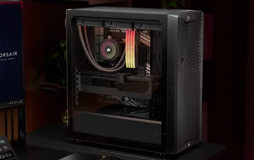
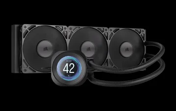
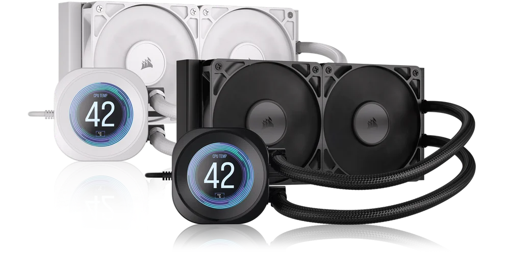
1. NAUTILUS RS LCD
NAUTILUS 240 RS LCD
NAUTILUS 360 RS LCD
2. RS FANS
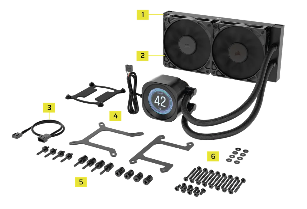
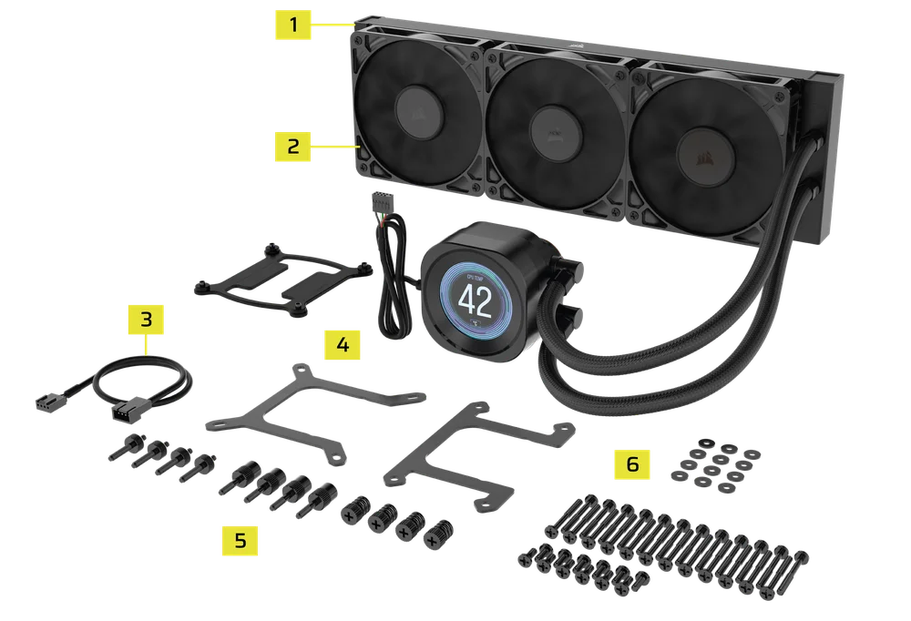
BOX CONTENTS
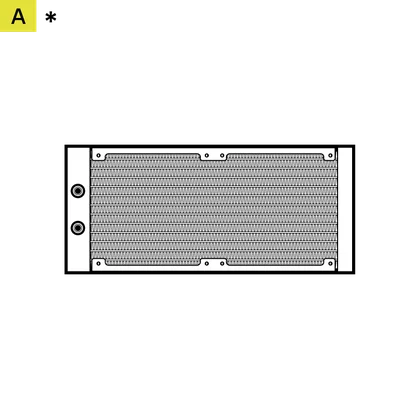
1x 240mm Radiator (240 RS LCD)
1x 360mm Radiator (360 RS LCD)
*240 shown
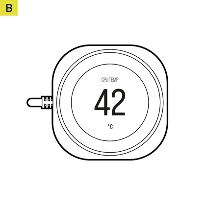
1x NAUTILUS RS Pump
with LCD Screen Module
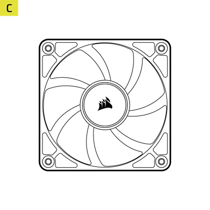
2x RS 120mm Fans (240 RS LCD)
3x RS 120mm Fans (360 RS LCD)

1x Intel LGA 1851/1700 Mounting Bracket
(pre-installed)
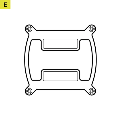
1x Intel LGA 1851/1700 Backplate
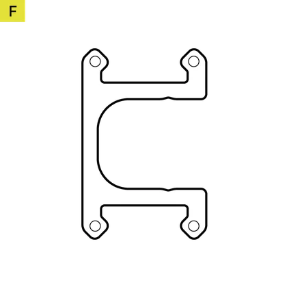
1x AMD AM5/AM4 Mounting Bracket
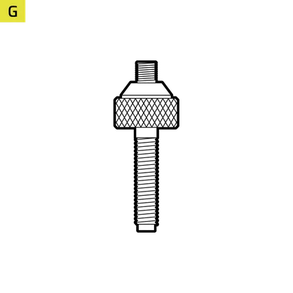
4x Intel LGA 1851/1700 Standoffs
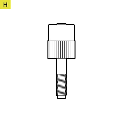
4x AMD AM5/AM4 Standoffs
4x Thumb Nuts
16x Long Fan Screws (240 RS LCD)
24x Long Fan Screws (360 RS LCD)
8x Radiator Screws (240 RS LCD)
12x Radiator Screws (360 RS LCD)

8x Washers (240 RS LCD)
12x Washers (360 RS LCD)
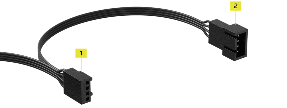
1x Fan PWM Extension Cable

PREPARE YOUR NAUTILUS RS LCD FOR INSTALLATION
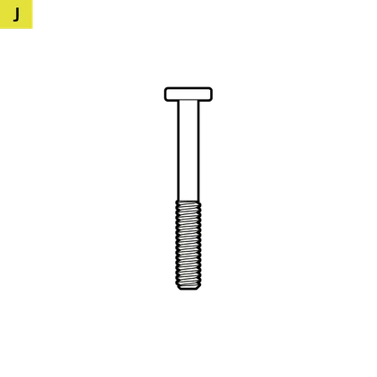
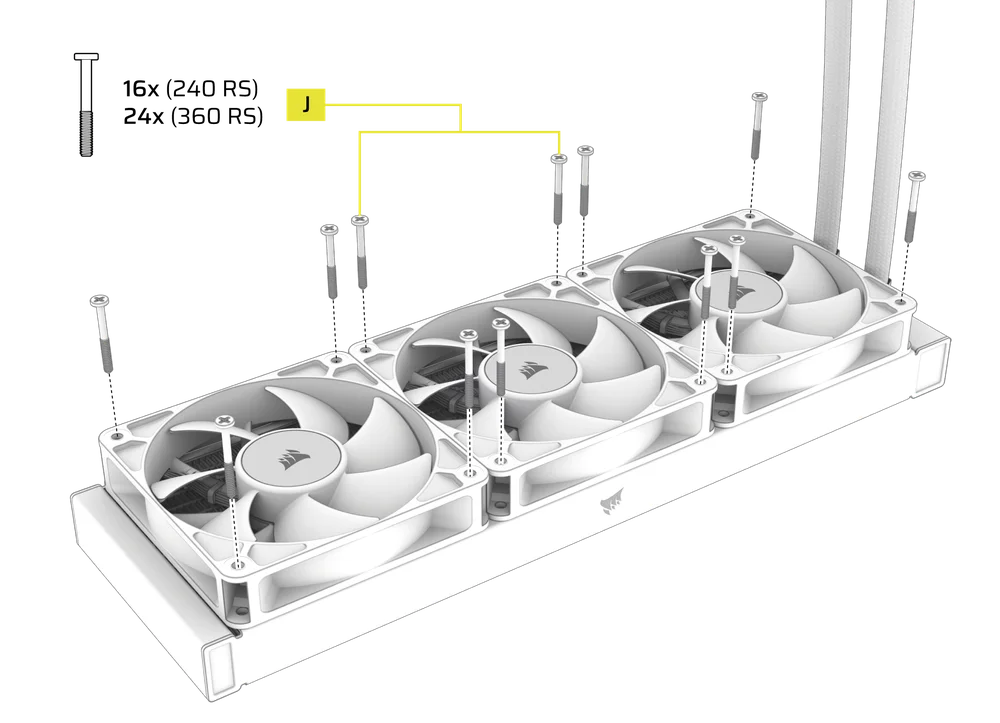
- Mount the fans onto the radiator with the Long Fan Screws (J) as shown.
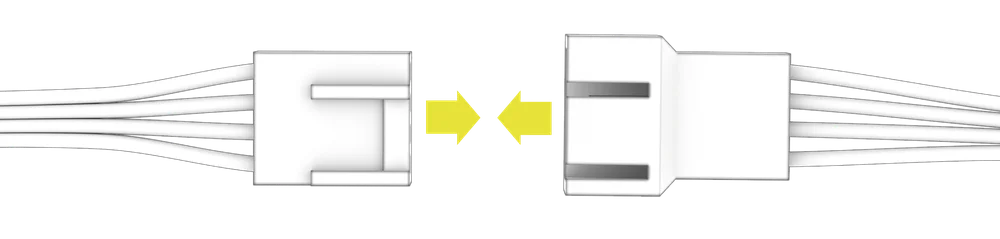
- Connect the 4-pin PWM cable from one RS fan into the 3-pin receptable of another RS fan to create a fan group.
INTEL INSTALLATION
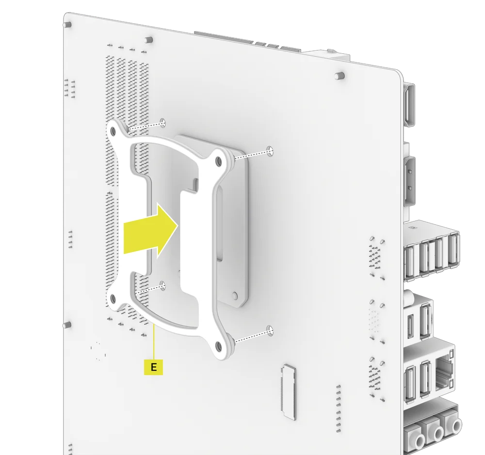
1. INSTALL THE BACKPLATE
- Align the Intel LGA 1851/1700 Backplate (E) then mount it behind the motherboard.
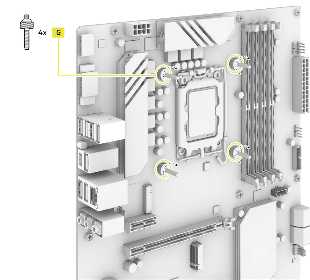
2. INSTALL THE INTEL STANDOFF SCREWS
- Attach and tighten the four provided Intel Standoffs (G).
3. INSTALL THE RADIATOR
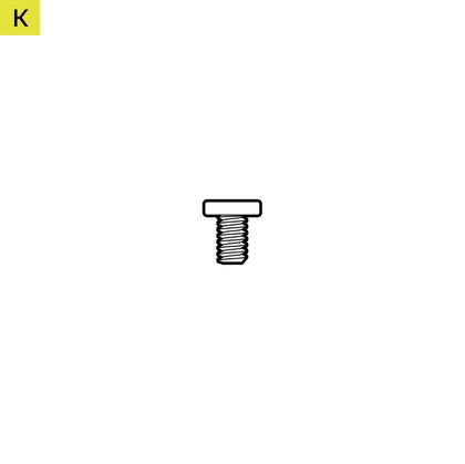
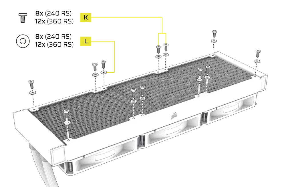
- Mount the radiator inside the case with the short screws (K) and washers (L) as shown.
4. INSTALL THE PUMP UNIT
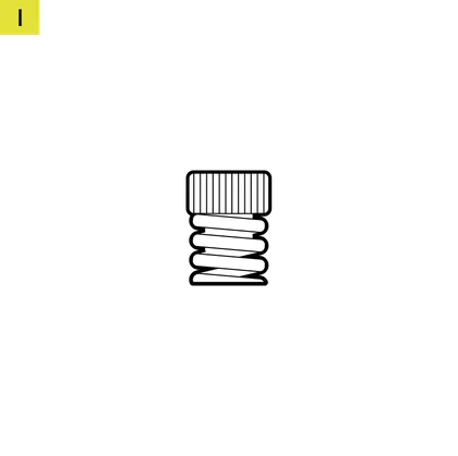
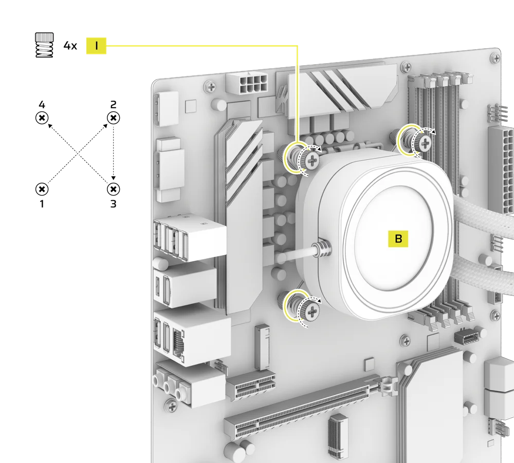
- Align the NAUTILUS RS Pump (B) with the pre-installed bracket over the standoffs, then secure it using the four included Thumb Nuts (I), tightening them in a cross pattern by alternating opposite corners.
AMD INSTALLATION
1. INSTALL THE AMD MOUNTING BRACKET
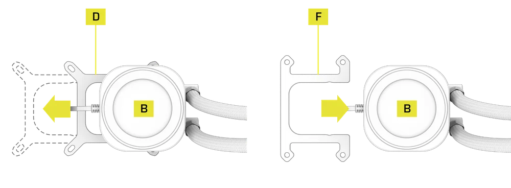
- Replace the pre-installed Intel LGA 1851/1700 Mounting Bracket (D) with the AMD AM5/AM4 Mounting Bracket (F).
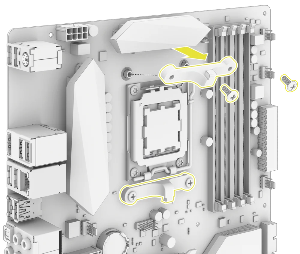
2. PREPARE THE MOTHERBOARD FOR INSTALLATION
- Remove the AMD AM5/AM4 motherboard brackets as shown.
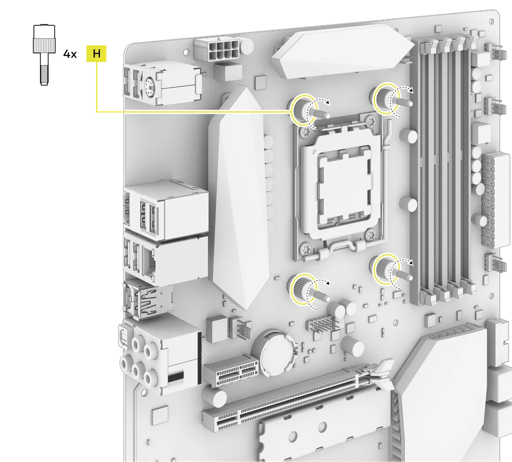
3. INSTALL THE AMD STANDOFF SCREWS
- Attach and tighten the four provided AMD AM5/AM4 Standoffs (H).
4. INSTALL THE RADIATOR
- Mount the radiator inside the case with the short screws (K) and washers (L) as shown.
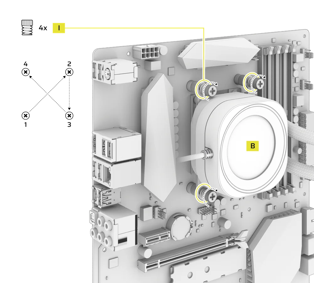
5. INSTALL THE PUMP UNIT
- Align the NAUTILUS RS Pump (B) with the bracket over the standoffs, then secure it using the four included Thumb Nuts (I), tightening them in a cross pattern by alternating opposite corners.
CONNECT YOUR NAUTILUS RS LCD
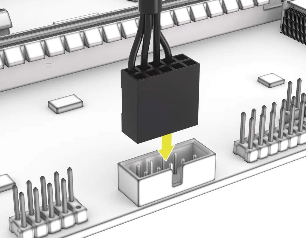
1. CONNECT THE LCD SCREEN MODULE
- Connect the USB 9-pin connector from the NAUTILUS RS Pump (B) LCD Screen Module into the USB 2.0 header on your motherboard so that the red wire is aligned with the power pin in the USB 2.0 header.
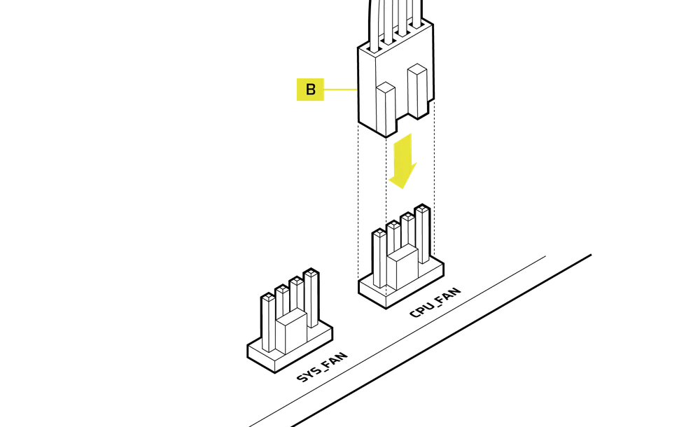
2. CONNECT THE NAUTILUS RS PUMP
- Connect the 4-pin PWM cable from the NAUTILUS RS Pump (B) to the CPU_FAN header on your motherboard.
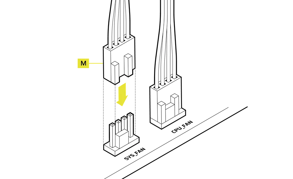
3. CONNECT THE FANS
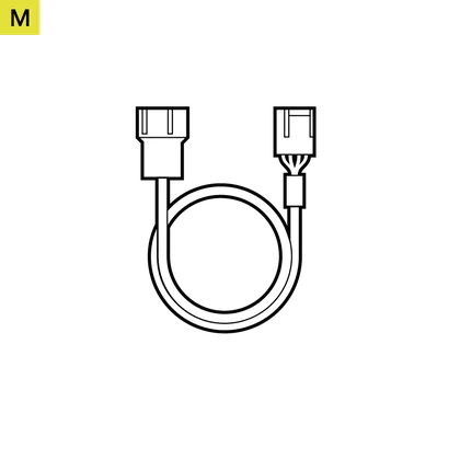
- Connect the Male PWM Connector of the Fan PWM Extension Cable (M) to the last fan cable.

- Connect the Female PWM Connector of the Fan PWM Extension Cable (M) to the SYS_FAN header on your motherboard.
SOFTWARE SETUP
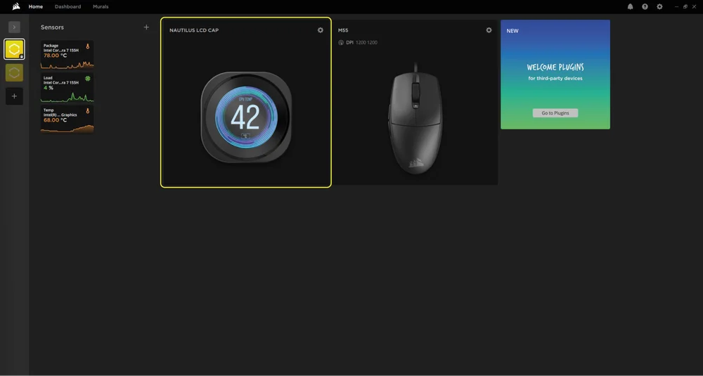
1. INSTALL iCUE
- Once iCUE is installed, run the software. The NAUTILUS LCD CAP will appear in the iCUE interface.
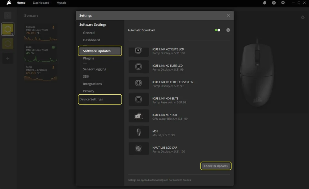
2. CHECK FOR UPDATES
- If any of the connected devices need a firmware update, you will be prompted to perform an update via a notification in the top right corner. You can also click the settings (cog wheel icon in the top right corner) and check for the software and firmware updates manually.
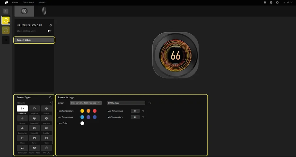
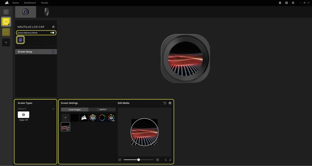
3. SCREEN SETUP
Choose which screen effect will be displayed when the iCUE software is running:
- Click "Screen Setup" to access the screen setup page.
- Select the a desired preset from the "Screen Types" panel.
- Adjust the selected preset in the "Screen Settings" panel.
4. DEVICE MEMORY MODE
Choose which screen effect will be displayed when the iCUE software is not running - usually during computer startup phase:
- Toggle the "Device Memory Mode" by clicking the button.
- In the “Screen Settings” panel, select one of the available images or upload your own.
- Click on the save icon to save the setting.
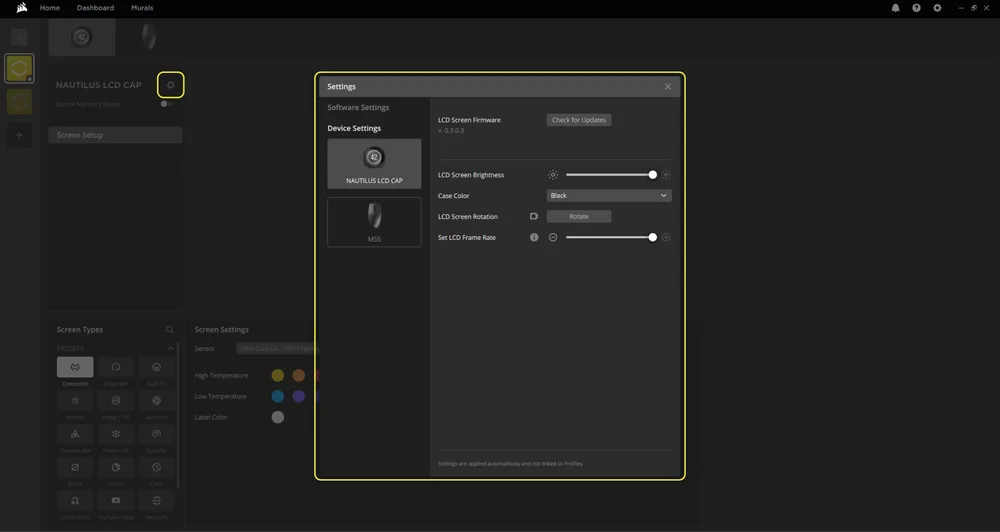
5. DEVICE SETTINGS
- Click the settings cog wheel icon next to the device name.
- Configure the screen brightness, device color, screen rotation and LCD frame rate.
ADDITIONAL SETUP
- Visit our CORSAIR LAB YouTube channel and Explorer page for additional setup, configuration and tips: CORSAIR LAB YouTube channel.
FREQUENTLY ASKED QUESTIONS
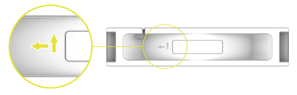
How do I know the direction of the airflow of the fan?
An arrow located on the side of the fan indicates the direction of airflow.
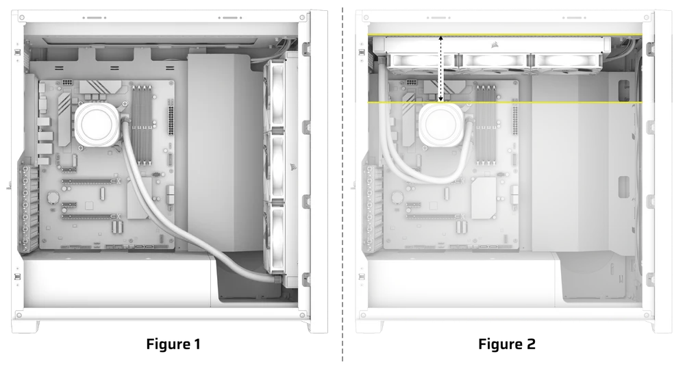
What orientation should I install my radiator?
For optimal performance, we recommend installing the radiator with the tubes positioned at the bottom of the case (Figure 1). However, you have the flexibility to install the radiator in various orientations, including an inverted position. Ensure that the highest point of the radiator is elevated above the level of the CPU pump, regardless of the installation orientation (Figure 2).
Can I reuse the pre-applied thermal paste on the cooler for re-installation?
Re-installation of the NAUTILUS Series CPU cooler will require you clean off the pre-applied thermal paste and apply a new layer of thermal paste. We recommend using CORSAIR XTM70, sold separately.
What should I do if I've lost or damaged a specific part of the NAUTILUS RS LCD CPU Cooler?
Replacement parts for the NAUTILUS RS CPU coolers are sold through the CORSAIR webstore.
How can I rotate my images and / or GIFs through iCUE software?
Once the LCD screen is recognized by iCUE software, images and GIFs shown on the screen can be adjusted, including uploading new content and changing orientation via the device settings in the software.
POWER RATING
NAUTILUS RS Pump: 12Vdc 0.3A MAX
NAUTILUS RS LCD Cap: 5Vdc 0.3A
RS120 Fan: 12Vdc 0.4A
WARRANTY

All CORSAIR NAUTILUS Series coolers have a 5-year warranty.
LEGAL
© 2025 CORSAIR MEMORY, Inc. All rights reserved. CORSAIR and the sails logo are registered trademarks of CORSAIR in the United States and/or other countries. All other trademarks are the property of their respective owners. Product may vary slightly from those pictured.
RELATED CONTENT